42-9
Catalyst 4500 Series Switch, Cisco IOS Software Configuration Guide - Cisco IOS XE 3.9.xE and IOS 15.2(5)Ex
Chapter 42 Configuring Policy-Based Routing
Policy-Based Routing Configuration Tasks
Use the set commands with each other. These commands are evaluated in the order shown in Step 3 in
the previous task table. A usable next hop implies an interface. Once the local switch finds a next hop
and a usable interface, it routes the packet.
Refer to the section Policy-Based Routing Configuration Examples, page 42-16 for examples of IPv4
PBR.
Use the show route-map map-tag command to display the existing route map.
Note Packet and byte counters in the output of the show route-map map-tag command are not updated.
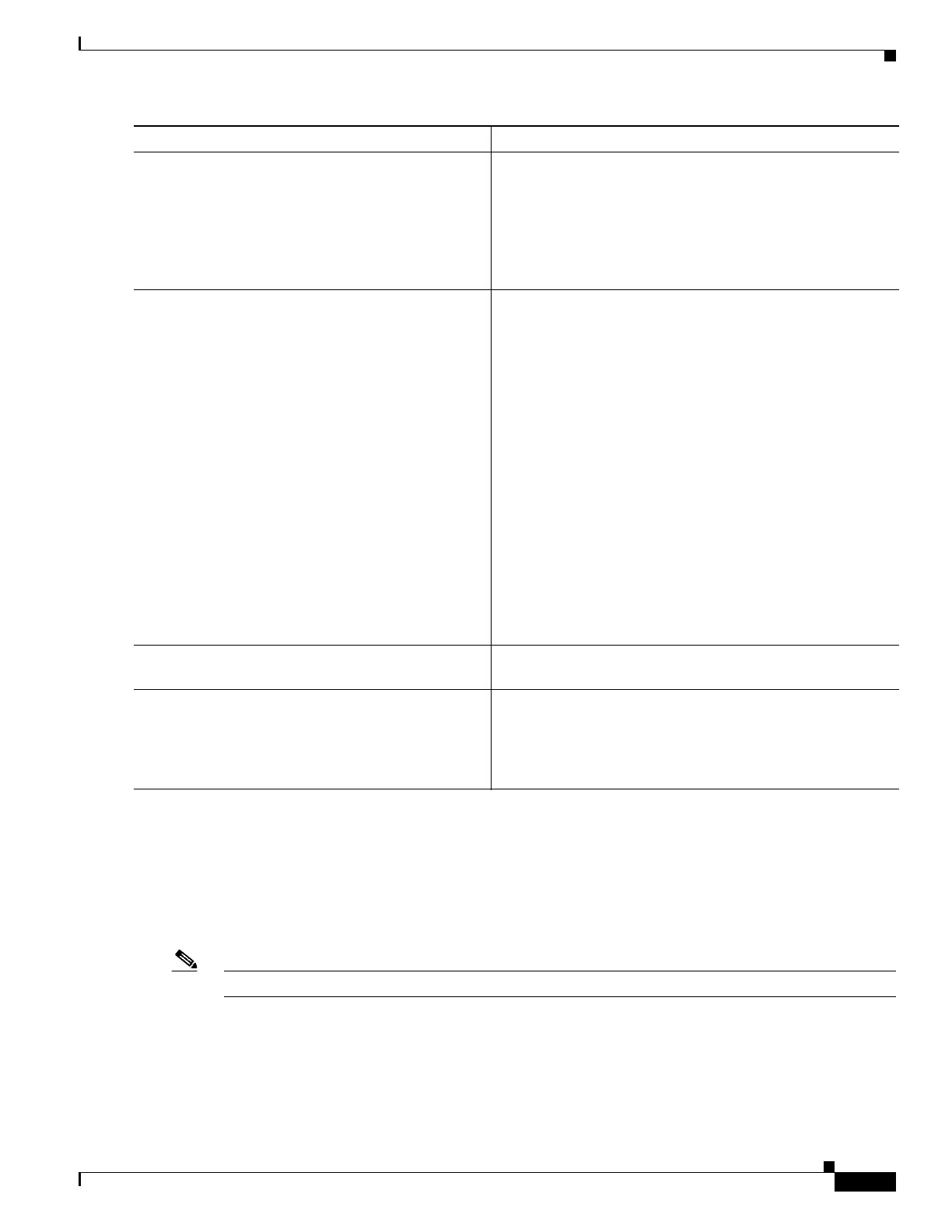
Step 7
Switch(config-route-map)# set ip default
next-hop ip-address [... ip-address]
Sets next hop to which to route the packet if there is no
explicit route for the destination IP address in the packet.
Before forwarding the packet to the next hop, the switch looks
up the packet’s destination address in the unicast routing
table. If a match is found, the packet is forwarded by way of
the routing table. If no match is found, the packet is forwarded
to the specified next hop.
Step 8
Switch(config-route-map)# set default
interface interface-type interface-number
[...type ...number]
Specifies the output interface from which the packet will be
sent if there is no explicit route for this destination. Before
forwarding the packet to the next hop, the switch looks up the
packet’s destination address in the unicast routing table. If a
match is found, the packet is forwarded by using the routing
table. If no match is found, the packet is forwarded to the
specified output interface.
Packets are forwarded on the specified interface only if one of
the following conditions is met:
• The destination IP address in the packet lies within the IP
subnet to which the specified interface belongs.
• The destination IP address in the packet is reachable
through the specified interface (as per the IP routing
table).
If the destination IP address on the packet does not meet
either of these conditions, the packet is dropped. This action
forces matching packets to be switched in software.
Step 9
Switch(config-route-map)# interface
interface-type interface-number
Specifies the interface. This command puts the switch into
interface configuration mode.
Step 10
Switch(config-if)# ip policy route-map map-tag
Identifies the route map to use for PBR. One interface can
only have one route map tag, but you can have multiple route
map entries with different sequence numbers. These entries
are evaluated in sequence number order until the first match.
If no match exists, packets are routed as usual.
Command Purpose

 Loading...


