23-3
Catalyst 4500 Series Switch, Cisco IOS Software Configuration Guide - Cisco IOS XE 3.9.xE and IOS 15.2(5)Ex
Chapter 23 Configuring STP and MST
About STP
Extended System ID
Extended system IDs are VLAN IDs between 1025 and 4096. Cisco IOS Releases 12.1(12c)EW and later
releases support a 12-bit extended system ID field as part of the bridge ID (see Table 23-2). Chassis that
support only 64 MAC addresses always use the 12-bit extended system ID. On chassis that support 1024
MAC addresses, you can enable use of the extended system ID. STP uses the VLAN ID as the extended
system ID. See the “Enabling the Extended System ID” section on page 23-9.
STP MAC Address Allocation
A Catalyst 4500 series switch chassis has either 64 or 1024 MAC addresses available to support software
features like STP. Enter the show module command to view the MAC address range on your chassis.
Cisco IOS Release 12.1(12c)EW and later releases support chassis with 64 or 1024 MAC addresses. For
chassis with 64 MAC addresses, STP uses the extended system ID plus a MAC address to make the
bridge ID unique for each VLAN.
Earlier releases support chassis with 1024 MAC addresses. With earlier releases, STP uses one MAC
address per-VLAN to make the bridge ID unique for each VLAN.
Bridge Protocol Data Units
The following elements determine the stable active spanning tree topology of a switched network:
• The unique bridge ID (bridge priority and MAC address) associated with each VLAN on each switch
• The spanning tree path cost (or bridge priority value) to the root bridge
• The port identifier (port priority and MAC address) associated with each Layer 2 interface
Bridge protocol data units (BPDUs) contain information about the transmitting bridge and its ports,
including the bridge and MAC addresses, bridge priority, port priority, and path cost. The system
computes the spanning tree topology by transmitting BPDUs among connecting switches, and in one
direction from the root switch. Each configuration BPDU contains at least the following:
• The unique bridge ID of the switch that the transmitting switch believes to be the root switch
• The spanning tree path cost to the root
• The bridge ID of the transmitting bridge
• The age of the message
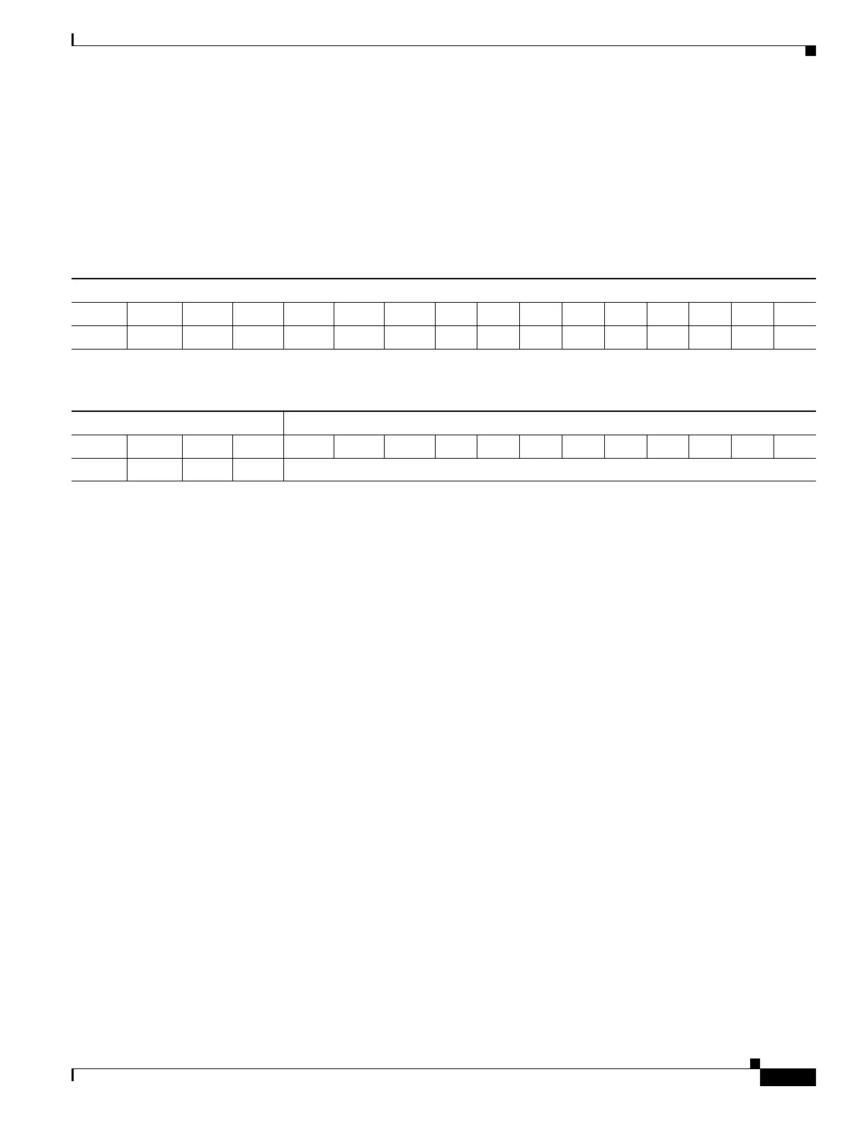
Table 23-1 Bridge Priority Value with the Extended System ID Disabled
Bridge Priority Value
Bit 16 Bit 15 Bit 14 Bit 13 Bit 12 Bit 11 Bit 10 Bit 9 Bit 8 Bit 7 Bit 6 Bit 5 Bit 4 Bit 3 Bit 2 Bit 1
32768 16384 8192 4096 2048 1024 512 256 128 64 32 16 8 4 2 1
Table 23-2 Bridge Priority Value and Extended System ID with the Extended System ID Enabled
Bridge Priority Value Extended System ID (Set Equal to the VLAN ID)
Bit 16 Bit 15 Bit 14 Bit 13 Bit 12 Bit 11 Bit 10 Bit 9 Bit 8 Bit 7 Bit 6 Bit 5 Bit 4 Bit 3 Bit 2 Bit 1
32768 16384 8192 4096 VLAN ID

 Loading...


