30-16
Catalyst 4500 Series Switch, Cisco IOS Software Configuration Guide - Cisco IOS XE 3.9.xE and IOS 15.2(5)Ex
Chapter 30 Configuring 802.1Q Tunneling, VLAN Mapping, and Layer 2 Protocol Tunneling
Configuring Layer 2 Protocol Tunneling
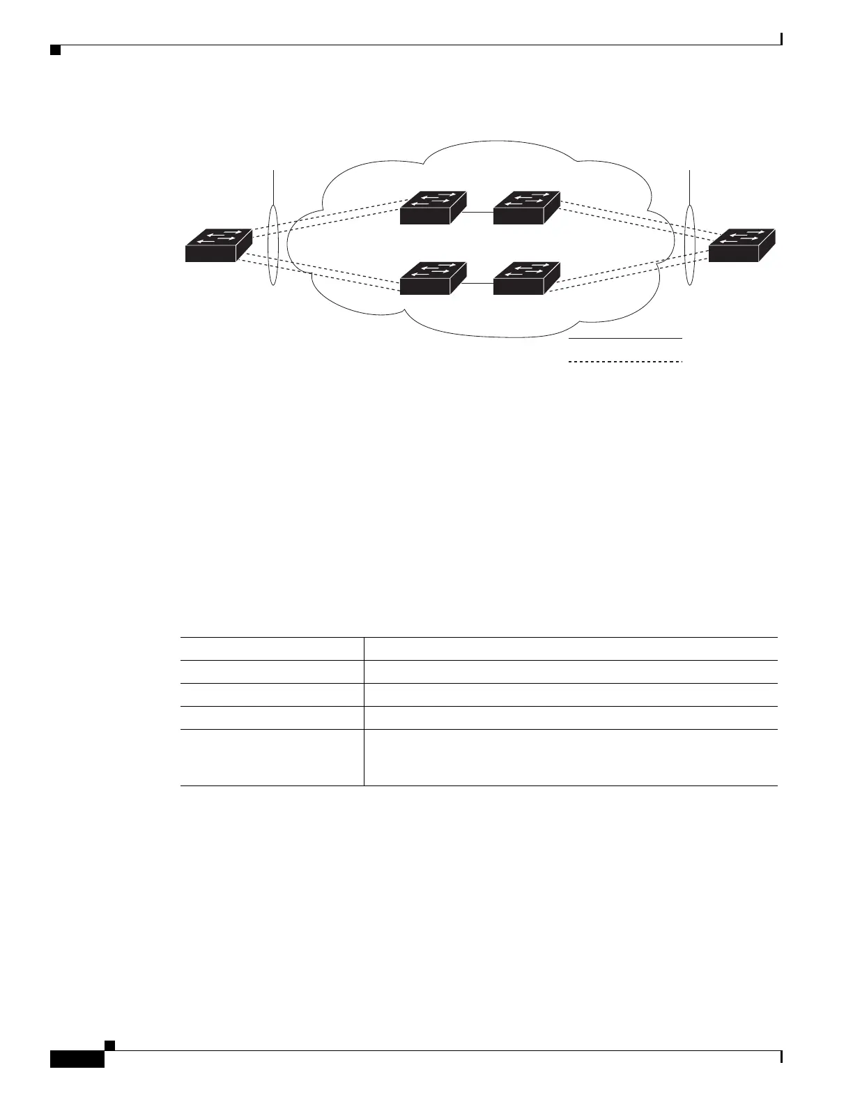
Figure 30-8 Layer 2 Protocol Tunneling for EtherChannels
This section contains the following subsections:
• Default Layer 2 Protocol Tunneling Configuration, page 30-16
• Layer 2 Protocol Tunneling Configuration Guidelines, page 30-16
• Configuring Layer 2 Tunneling, page 30-17
• Configuring Layer 2 Tunneling for EtherChannels, page 30-19
Default Layer 2 Protocol Tunneling Configuration
Table 30-1 shows the default configuration for Layer 2 protocol tunneling.
Layer 2 Protocol Tunneling Configuration Guidelines
These are some configuration guidelines and operating characteristics of Layer 2 protocol tunneling:
• The switch supports tunneling of CDP, STP, including multiple STP (MSTP), and VTP. Protocol
tunneling is disabled by default but can be enabled for the individual protocols on 802.1Q tunnel
ports, access ports or trunk ports.
• Dynamic Trunking Protocol (DTP) is not compatible with Layer 2 protocol tunneling because you
must manually configure asymmetric links with tunnel ports and trunk ports.
Sw i t c h A
VLAN 17
VLAN 18
VLAN 19
VLAN 20
VLAN 17
VLAN 18
VLAN 19
VLAN 20
Sw i t c h B
Sw i t c h C
Se r v i c e
Pr o v i d e r
EtherChannel 1
Cu st o m er A
Site 1
Cu st o m er A
Site 2
101844
Sw i t c h D
EtherChannel 1
Tr u n k
Asymmetric link
Table 30-1 Default Layer 2 Ethernet Interface VLAN Configuration
Feature Default Setting
Layer 2 protocol tunneling Disabled.
Shutdown threshold None set.
Drop threshold None set.
CoS value If a CoS value is configured on the interface for data packets, that
value is the default used for Layer 2 PDUs. If none is configured, the
default is 5.

 Loading...


