35-2
Catalyst 4500 Series Switch, Cisco IOS Software Configuration Guide - Cisco IOS XE 3.9.xE and IOS 15.2(5)Ex
Chapter 35 Configuring Layer 3 Interfaces
About Layer 3 Interfaces
This section contains the following subsections:
• Logical Layer 3 VLAN Interfaces, page 35-2
• Physical Layer 3 Interfaces, page 35-2
• Understanding SVI Autostate Exclude, page 35-3
• Understanding Layer 3 Interface Counters, page 35-3
Logical Layer 3 VLAN Interfaces
The logical Layer 3 VLAN interfaces provide logical routing interfaces to VLANs on Layer 2 switches.
A traditional network requires a physical interface from a router to a switch to perform inter-VLAN
routing. The Catalyst 4500 series switch supports inter-VLAN routing by integrating the routing and
bridging functions on a single Catalyst 4500 series switch.
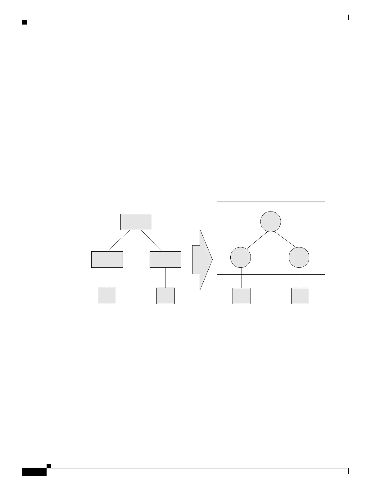
Figure 35-1 shows how the routing and bridging functions in the three physical devices of the traditional
network are performed logically on one Catalyst 4500 series switch.
Figure 35-1 Logical Layer 3 VLAN Interfaces for the Catalyst 4500 Series Switch
Physical Layer 3 Interfaces
The physical Layer 3 interfaces support capabilities equivalent to a traditional router. These Layer 3
interfaces provide hosts with physical routing interfaces to a Catalyst 4500 series switch.
Figure 35-2 shows how the Catalyst 4500 series switch functions as a traditional router.
L2 Switch L2 Switch
Router
Host 1 Host 2
Traditional network topology for routing
between VLANS
Host 1 Host 2
Logical Inter-VLAN routing on a single
Catalyst 4500 series switch
Routing
VLAN1 VLAN2
VLAN1 VLAN2
94169
Interface Ethernet
1.1.1.1
Interface VLAN1
1.1.1.1
Interface VLAN2
2.1.1.1
Interface Ethernet
2.1.1.1

 Loading...


