30-8
Catalyst 4500 Series Switch, Cisco IOS Software Configuration Guide - Cisco IOS XE 3.9.xE and IOS 15.2(5)Ex
Chapter 30 Configuring 802.1Q Tunneling, VLAN Mapping, and Layer 2 Protocol Tunneling
About VLAN Mapping
• Traditional 802.1Q tunneling (QinQ) performs all-to-one bundling of C-VLAN IDs to a single
S-VLAN ID for the port. The S-VLAN is added to the incoming unmodified C-VLAN. You can
configure the UNI as an 802.1Q tunnel port for traditional QinQ, or you can configure selective
QinQ on trunk ports for a more flexible implementation. Mapping takes place at ingress and egress
of the port. All packets on the port are bundled into the specified S-VLAN. See the “Traditional
Q-in-Q on a Trunk Port” section on page 30-11.
• Selective QinQ maps the specified customer VLANs entering the UNI to the specified S-VLAN ID.
The S-VLAN is added to the incoming unmodified C-VLAN. You can also specify whether traffic
carrying all other customer VLAN IDs should be dropped or not. See the “Selective Q-in-Q on a
Trunk Port” section on page 30-12.
Note Untagged packets enter the switch on the trunk native VLAN and are not mapped.
For quality of service (QoS), the switch supports flexible mapping between C-CoS or C-DSCP and
S-CoS, and maps the inner CoS to the outer CoS for traffic with traditional QinQ or selective QinQ
VLAN mapping.
Mapping Customer VLANs to Service-Provider VLANs
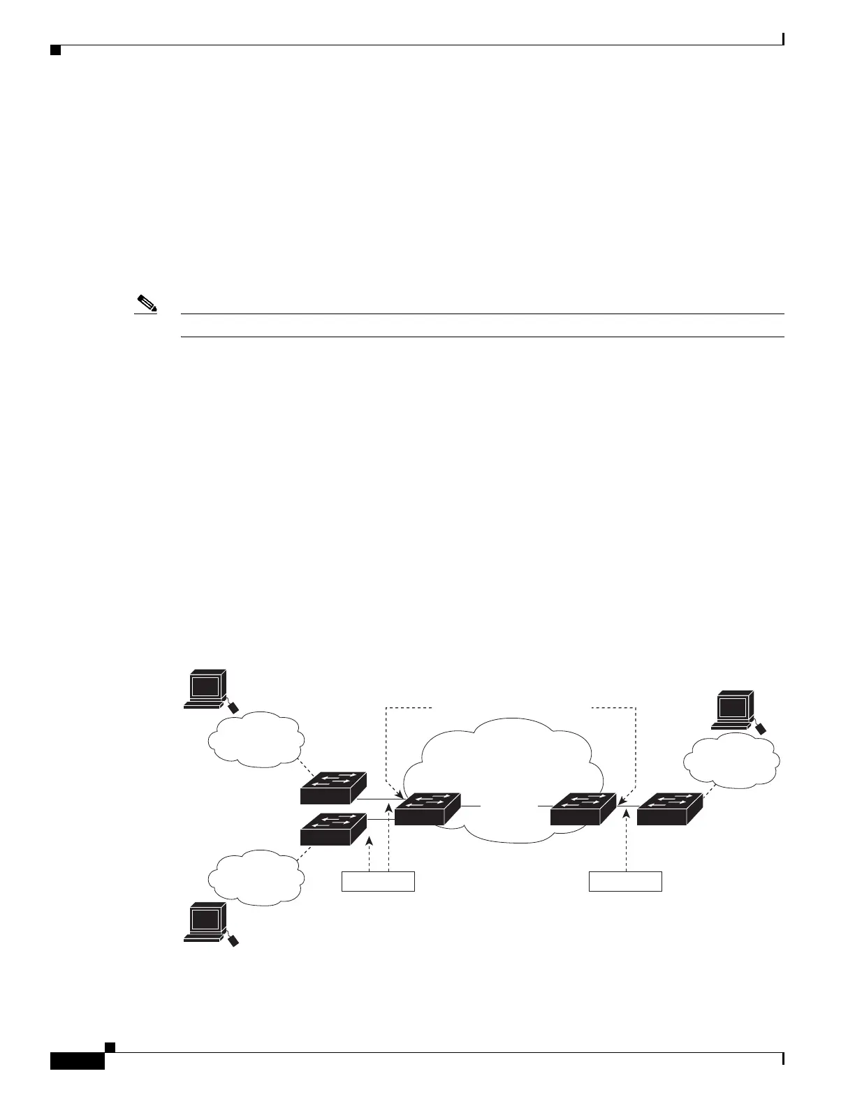
Figure 30-5 shows a topology where a customer uses the same VLANs in multiple sites on different sides
of a service-provider network. You map the customer VLAN IDs to service-provider VLAN IDs for
packet travel across the service-provider backbone. The customer VLAN IDs are retrieved at the other
side of the service-provider backbone for use in the other customer site. Configure the same set of VLAN
mappings at a customer-connected port on each side of the service-provider network.
The examples following the configuration steps illustrate how to use one-to-one mapping, traditional
QinQ, or selective QinQ to map customer VLANs 1 to 5 to service-provider VLANs.
Figure 30-5 Mapping Customer VLANs
Service provider
Customer A
VLANs 1-5
Host
Host
Customer A
VLANs 1-5
Customer A
VLANs 1-5
Customer
switches
Customer
switch
Trunk port Trunk port
VLAN mapping at
customer-connecting ports
278036
Switch A Switch B

 Loading...


