35-14
Catalyst 4500 Series Switch, Cisco IOS Software Configuration Guide - Cisco IOS XE 3.9.xE and IOS 15.2(5)Ex
Chapter 35 Configuring Layer 3 Interfaces
Configuring EIGRP Stub Routing
The IP base image contains only EIGRP stub routing. The IP services image contains complete EIGRP
routing.
In a network using EIGRP stub routing, the only route for IP traffic to follow to the user is through a
switch that is configured with EIGRP stub routing. The switch sends the routed traffic to interfaces that
are configured as user interfaces or are connected to other devices.
When using EIGRP stub routing, you need to configure the distribution and remote switches to use
EIGRP, and to configure only the switch as a stub. Only specified routes are propagated from the switch.
The switch responds to all queries for summaries, connected routes, and routing updates.
Any neighbor that receives a packet informing it of the stub status does not query the stub switch for any
routes, and a switch that has a stub peer does not query that peer. The stub switch depends on the
distribution switch to send the proper updates to all peers.
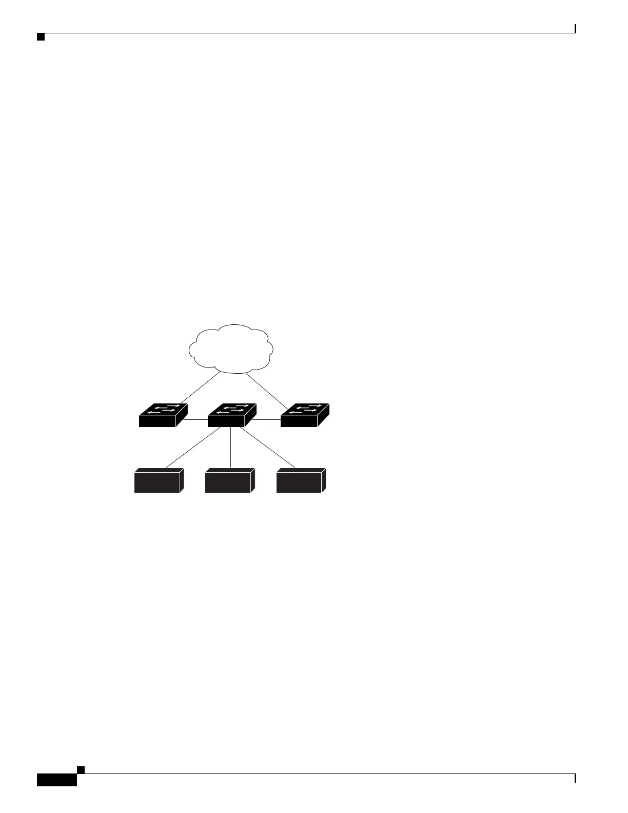
In Figure 35-3, switch B is configured as an EIGRP stub switch. Switches A and C are connected to the
rest of the WAN. Switch B advertises connected, static, redistribution, and summary routes from switch
A and C to Hosts A, B, and C. Switch B does not advertise any routes learned from switch A (and the
reverse).
Figure 35-3 EIGRP Stub Switch Configuration
For more information about EIGRP stub routing, see the “Configuring EIGRP Stub Routing” part of the
Cisco IOS IP Configuration Guide, Volume 2 of 3: Routing Protocols, Release 12.2.
Configuring EIGRP Stub Routing
The EIGRP stub routing feature improves network stability, reduces resource utilization, and simplifies
stub switch configuration.
Stub routing is commonly used in a hub-and-spoke network topology. In a hub-and-spoke network, one
or more end (stub) networks are connected to a remote switch (the spoke) that is connected to one or
more distribution switches (the hub). The remote switch is adjacent only to one or more distribution
switches. The only route for IP traffic to follow into the remote switch is through a distribution switch.
This type of configuration is commonly used in WAN topologies where the distribution switch is directly
connected to a WAN. The distribution switch can be connected to many more remote switches. Often,
the distribution switch is connected to 100 or more remote routers. In a hub-and-spoke topology, the
Host A Host B
Switch B
Switch A
Routed to WAN
Switch C
Host C
145776

 Loading...


