38-6
Catalyst 4500 Series Switch, Cisco IOS Software Configuration Guide - Cisco IOS XE 3.9.xE and IOS 15.2(5)Ex
Chapter 38 Configuring IP Multicast
About IP Multicast
CEF, MFIB, and Layer 2 Forwarding
The implementation of IP multicast on the Catalyst 4500 series switch is an extension of centralized
Cisco Express Forwarding (CEF). CEF extracts information from the unicast routing table, which is
created by unicast routing protocols, such as BGP, OSPF, and EIGRP and loads it into the hardware
Forwarding Information Base (FIB). With the unicast routes in the FIB, when a route is changed in the
upper-layer routing table, only one route needs to be changed in the hardware routing state. To forward
unicast packets in hardware, the Integrated Switching Engine looks up source and destination routes in
ternary content addressable memory (TCAM), takes the adjacency index from the hardware FIB, and
gets the Layer 2 rewrite information and next-hop address from the hardware adjacency table.
The new Multicast Forwarding Information Base (MFIB) subsystem is the multicast analog of the
unicast CEF. The MFIB subsystem extracts the multicast routes that PIM and IGMP create and refines
them into a protocol-independent format for forwarding in hardware. The MFIB subsystem removes the
protocol-specific information and leaves only the essential forwarding information. Each entry in the
MFIB table consists of an (S,G) or (*,G) route, an input RPF VLAN, and a list of Layer 3 output
interfaces. The MFIB subsystem, together with platform-dependent management software, loads this
multicast routing information into the hardware FIB and Replica Expansion Table (RET).
The Catalyst 4500 series switch performs Layer 3 routing and Layer 2 bridging at the same time. There
can be multiple Layer 2 switch ports on any VLAN interface.
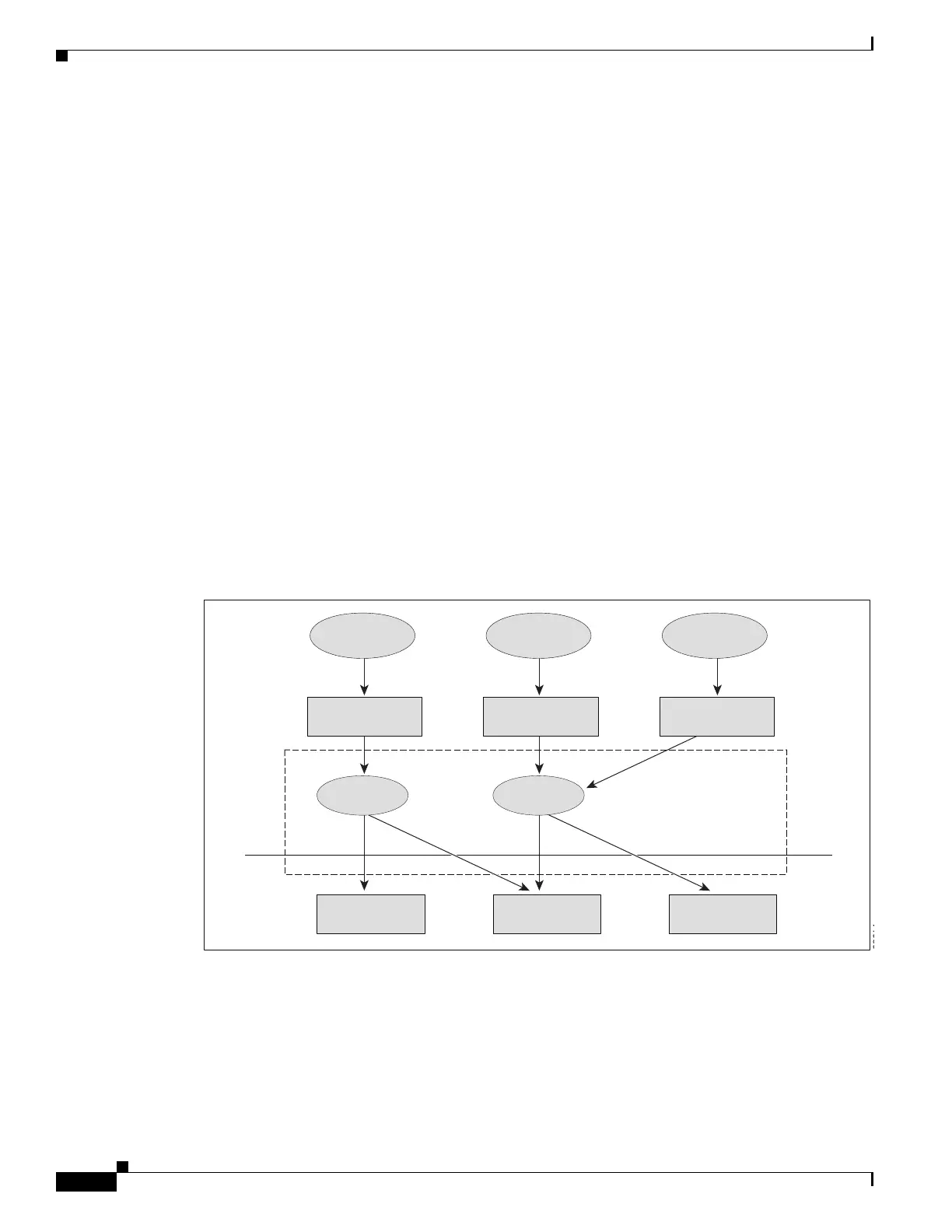
Figure 38-3 shows a functional overview of how the Catalyst 4500 series switch combines unicast
routing, multicast routing, and Layer 2 bridging information to forward in hardware.
Figure 38-3 Combining CEF, MFIB, and Layer 2 Forwarding Information in Hardware
Like the CEF unicast routes, the MFIB routes are Layer 3 and must be merged with the appropriate
Layer 2 information. The following example shows an MFIB route:
(*,224.1.2.3)
RPF interface is Vlan3
Output Interfaces are:
Vlan 1
Vlan 2
Unicast Routing
Table
Multicast Routing
Table
Layer 2 Forwarding
Table
H/W FIB
Table
H/W Adjacency
Table
MET Replication
Table
Protocols
Hardware
Tables
Software
Tables
Unicast Multicast
CEF – MFIB Subsystem
CPU
Subsystem
Software
Integrated
Switching
Engine
L2 Multicast
OSPF PIM / IGMP
IGMP Snooping
Spanning Tree
CEF MFIB
68614

 Loading...


