35-11
Catalyst 4500 Series Switch, Cisco IOS Software Configuration Guide - Cisco IOS XE 3.9.xE and IOS 15.2(5)Ex
Chapter 35 Configuring Layer 3 Interfaces
Configuring VLANs as Layer 3 Interfaces
Global unicast address(es):
1001::1, subnet is 1001::/64
Joined group address(es):
FF02::1
FF02::1:FF00:1
FF02::1:FFBC:DEEA
MTU is 1280 bytes
...................(continued)
Note When IPv6 is enabled on an interface using any CLI command, you may see the following message:
% Hardware MTU table exhausted
In this situation, the IPv6 MTU value programmed in hardware differs from the IPv6 interface MTU
value. This situation occurs if no room exists in the hardware MTU table to store additional values. You
must free up some space in the table by unconfiguring some unused MTU values and subsequently
disable and reenable IPv6 on the interface or reapply the MTU configuration.
Configuring Layer 3 Interface Counters
Note Catalyst 4900M, Catalyst 4948E, Supervisor Engine 6-E, Supervisor Engine 6L-E, Supervisor Engine
7-E, Supervisor Engine 7L-E, and Supervisor Engine 8-E, do not support Layer 2 interface counters.
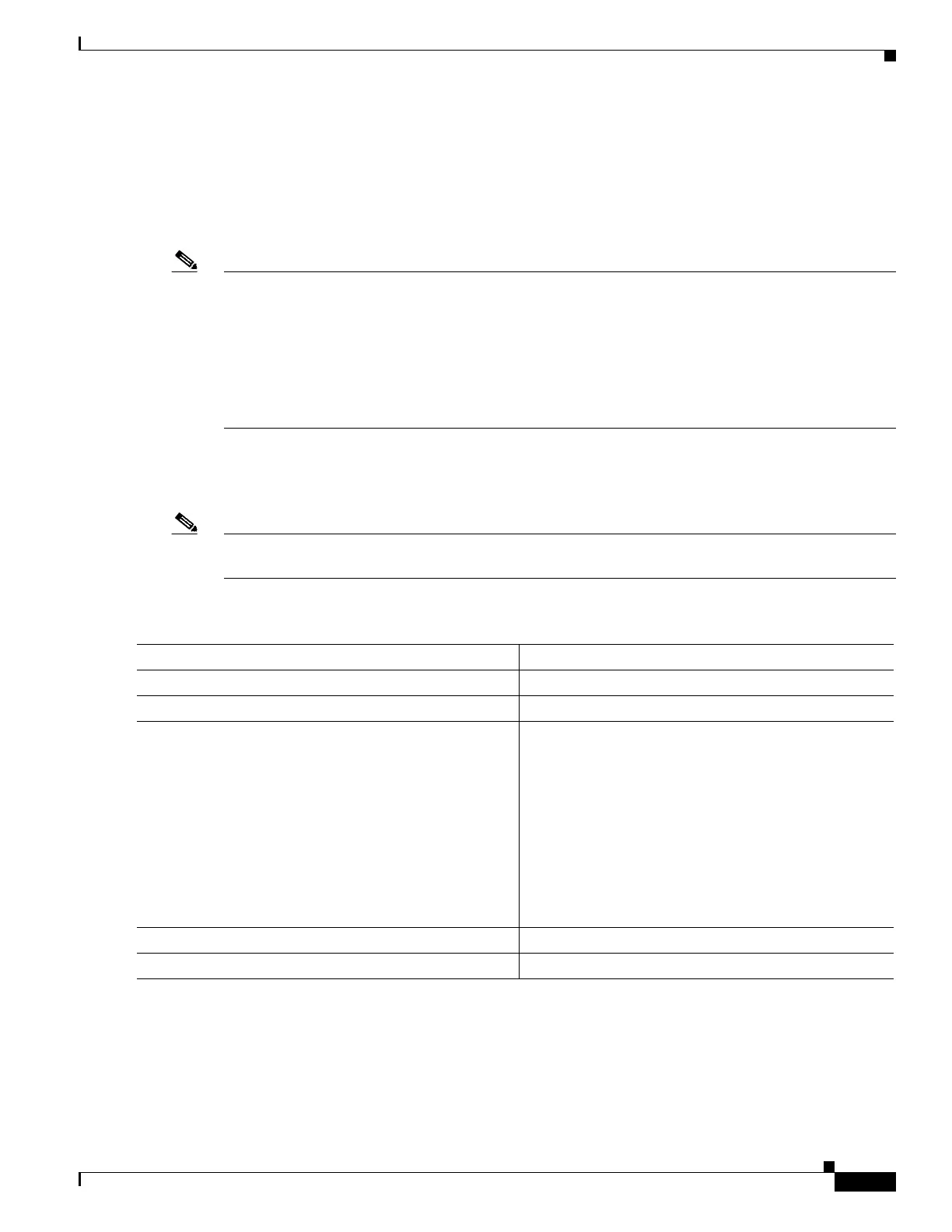
To configure Layer 3 interface counters (assign counters to a Layer 3 interface), perform this task:
This example shows how to enable counters on interface VLAN 1:
Switch# configure terminal
Enter configuration commands, one per line. End with CNTL/Z.
Switch(config)# interface vlan 1
Switch(config-if)# counter ipv4
Switch(config-if)# end
Command Purpose
Step 1
Switch# configure terminal
Enters global configuration mode.
Step 2
Switch(config)# interface interface-id
Enters interface configuration mode.
Step 3
Switch(config-if)# counter {ipv4 | ipv6 | ipv4
ipv6 separate>
Enables counters.
counter —Enables collection of IPv4 and IPv6 statistics
and displays them as a sum
counter ipv4 — Enables collection of IPv4 statistics
only
counter ipv6 — Enables collection of IPv6 statistics
only
counter ipv4 ipv6 separate —Enables collection of
IPv4 and IPv6 statistics and displays them individually
Step 4
Switch(config)# end
Exits configuration mode.
Step 5
Switch# show run interface interface-id
Displays the running configuration.

 Loading...


