76-3
Catalyst 4500 Series Switch, Cisco IOS Software Configuration Guide - Cisco IOS XE 3.9.xE and IOS 15.2(5)Ex
Chapter 76 Configuring Y.1731 (AIS and RDI)
About Y.1731
for an interface. A MEP continues to transmit periodic frames with ETH-AIS information until the defect
condition is removed. Upon receiving a frame with ETH-AIS information, a MEP detects AIS condition
and suppresses loss of continuity alarms associated with all its peer MEPs. A MEP resumes loss of
continuity alarm generation upon detecting loss of continuity defect conditions in the absence of AIS
condition.
Ethernet Remote Defect Indication
A MEP can use ETH-RDI to notify its peer MEPs that it detects a defect condition. ETH-RDI is used
only when ETH-CC transmission is enabled.
ETH-RDI has the following two applications:
• Single-ended fault management—The receiving MEP detects an RDI defect condition, which is
correlated with other defect conditions in this MEP and may cause a fault. The absence of received
ETH-RDI information in a single MEP indicates the absence of defects in the entire maintenance.
• Contribution to far-end performance monitoring— It reflects a defect condition in the far-end which
serves as input to the performance monitoring process.
A MEP that is in a defect condition transmits frames with ETH-RDI information. A MEP, upon receiving
frames with ETH-RDI information, determines that its peer MEP has encountered a defect condition.
For multipoint ETH connectivity, however, a MEP, upon receiving frames with ETH-RDI information,
cannot determine the associated subset of its peer MEPs with which the MEP transmitting RDI
information encounters defect conditions. it is because the transmitting MEP itself does not always have
that information.
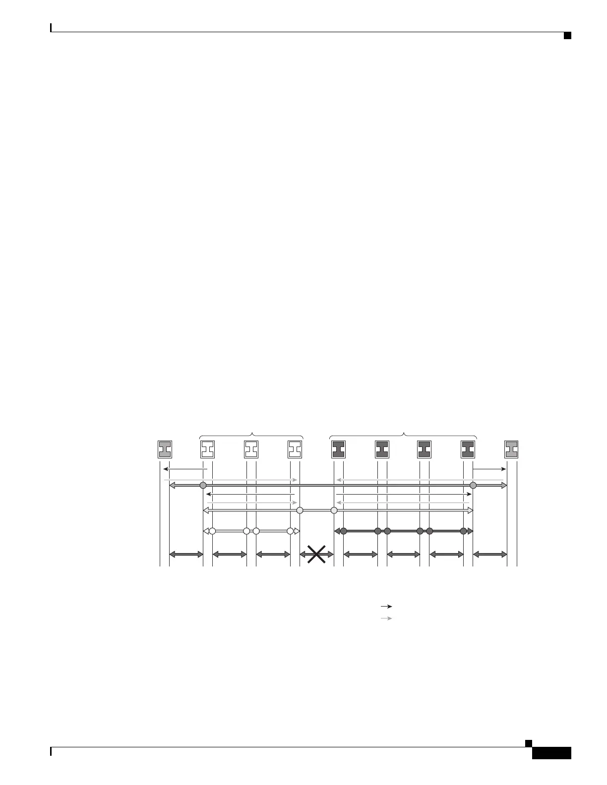
Figure 76-1 Generating and Propagating AIS Messages Upon a Defect (Link Fail)
Customer
Equipment
Operator A Bridges Operator B Bridges
Customer
Equipment
280624
MM MM
MM
MM
MMMMMMM
MM
MM
LLLLL
LLLLLLLLLLLMMMMMM
LLLLLLLL LLLLLLLL
MMMMM MMMMM MMMMM MMMMM MMMMM MMMMM MM
= Maintenance End Point
= Maintenance Intermediate Point
= AIS
= CC with RDI
MM
LL
7
4
3

 Loading...


