14-14
Catalyst 4500 Series Switch, Cisco IOS Software Configuration Guide - Cisco IOS XE 3.9.xE and IOS 15.2(5)Ex
Chapter 14 Environmental Monitoring and Power Management
Power Management
The following example shows how to set the power management mode to combined mode:
Switch(config)# power redundancy-mode combined
Switch(config)# end
Switch#
The following example shows how to display the current power redundancy mode. The power supplies
needed by system: 2 indicates that the switch is in combined mode.
Switch# show power supplies
Power supplies needed by system:2
Switch#
Available Power for Catalyst 4500 Series Switches Power Supplies
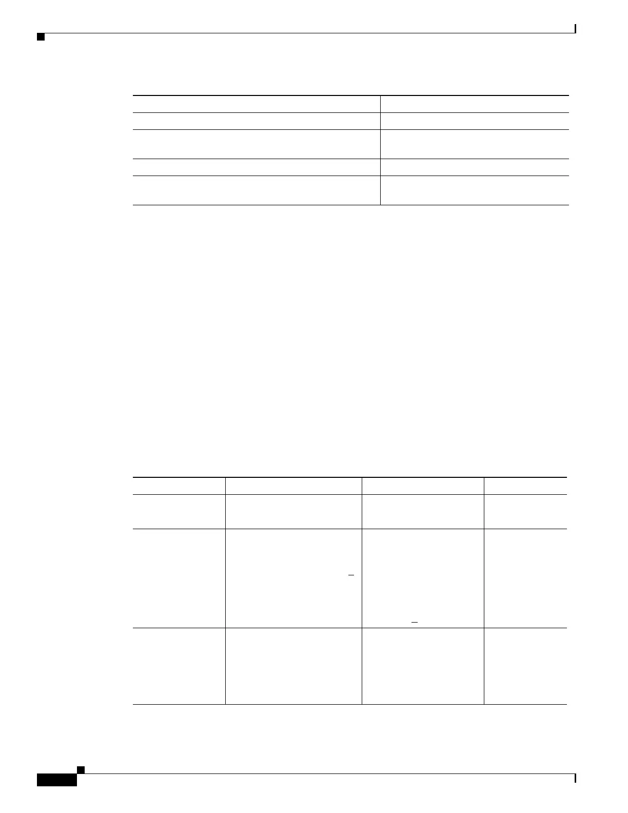
Table 14-5 lists the power available for use in the various Catalyst 4500 series switches power supplies.
When your switch is configured to combined mode, the total available power in not the mathematical
sum of the individual power supplies. The power supplies have a sharing ratio predetermined by the
hardware. In combined mode, the total power available is P + (P * sharing-ratio), where P is the amount
of power in the power supply.
Command Purpose
Step 1
Switch# configure terminal Enters configuration mode.
Step 2
Switch(config)# power redundancy-mode combined
Sets the power management mode to
combined mode.
Step 3
Switch(config)# end
Exits configuration mode.
Step 4
Switch# show power supplies Verifies the power redundancy mode for
the switch.
Table 14-5 Available Power for Switch Power Supplies
Power Supply Redundant Mode (W) Combined Mode (W) Sharing Ratio
1000 W AC Chassis
1
= 1050
PoE = 0
Chassis = 1667
PoE = 0
2/3
1300 W AC Chassis (max) = 1050
PoE (max) = 800
Chassis + PoE + Backplane <
1300
Chassis (min) = 767
PoE (max) = 1333
Chassis (max) = 1667
PoE (min) = 533
Chassis + PoE +
Backplane <
2200
2/3
1400 W DC Chassis (min) = 200
Chassis (max) = 1360
PoE (max)
2
= (DC Input
3
-
[Chassis (min) + Backplane] /
0.75) * 0.96
Chassis = 2267
4
PoE
5
Chassis—2/3
PoE—0

 Loading...


