5-2
Catalyst 4500 Series Switch, Cisco IOS Software Configuration Guide - Cisco IOS XE 3.9.xE and IOS 15.2(5)Ex
Chapter 5 Configuring Virtual Switching Systems
Understanding Virtual Switching Systems
• VSS Initialization, page 5-26
VSS Overview
Network operators increase network reliability by configuring switches and by provisioning links to the
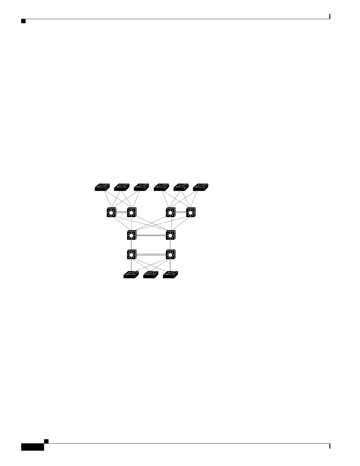
redundant pairs. Figure 5-1 shows a typical switch network configuration. Redundant network elements
and redundant links can add complexity to network design and operation. Virtual switching simplifies
the network by reducing the number of network elements and hiding the complexity of managing
redundant switches and links.
A VSS combines a pair of Catalyst 4500 or 4500-X series switches into a single network element. The
VSS manages the redundant links, which externally act as a single port channel.
The VSS simplifies network configuration and operation by reducing the number of Layer 3 routing
neighbors and by providing a loop-free Layer 2 topology.
Figure 5-1 Typical Switch Network Design
The following sections present an overview of the VSS. These topics are covered in detail in subsequent
chapters:
• Key Concepts, page 5-2
• VSS Functionality, page 5-5
• Hardware Requirements, page 5-8
• Understanding VSL Topology, page 5-10
Key Concepts
The VSS incorporates the following key concepts:
• Virtual Switching System, page 5-3
• VSS Active and VSS Standby Switch, page 5-3
• Virtual Switch Link, page 5-3
• Multichassis EtherChannel, page 5-4
Access
Distribution
Core
181320

 Loading...


