5-3
Catalyst 4500 Series Switch, Cisco IOS Software Configuration Guide - Cisco IOS XE 3.9.xE and IOS 15.2(5)Ex
Chapter 5 Configuring Virtual Switching Systems
Understanding Virtual Switching Systems
Virtual Switching System
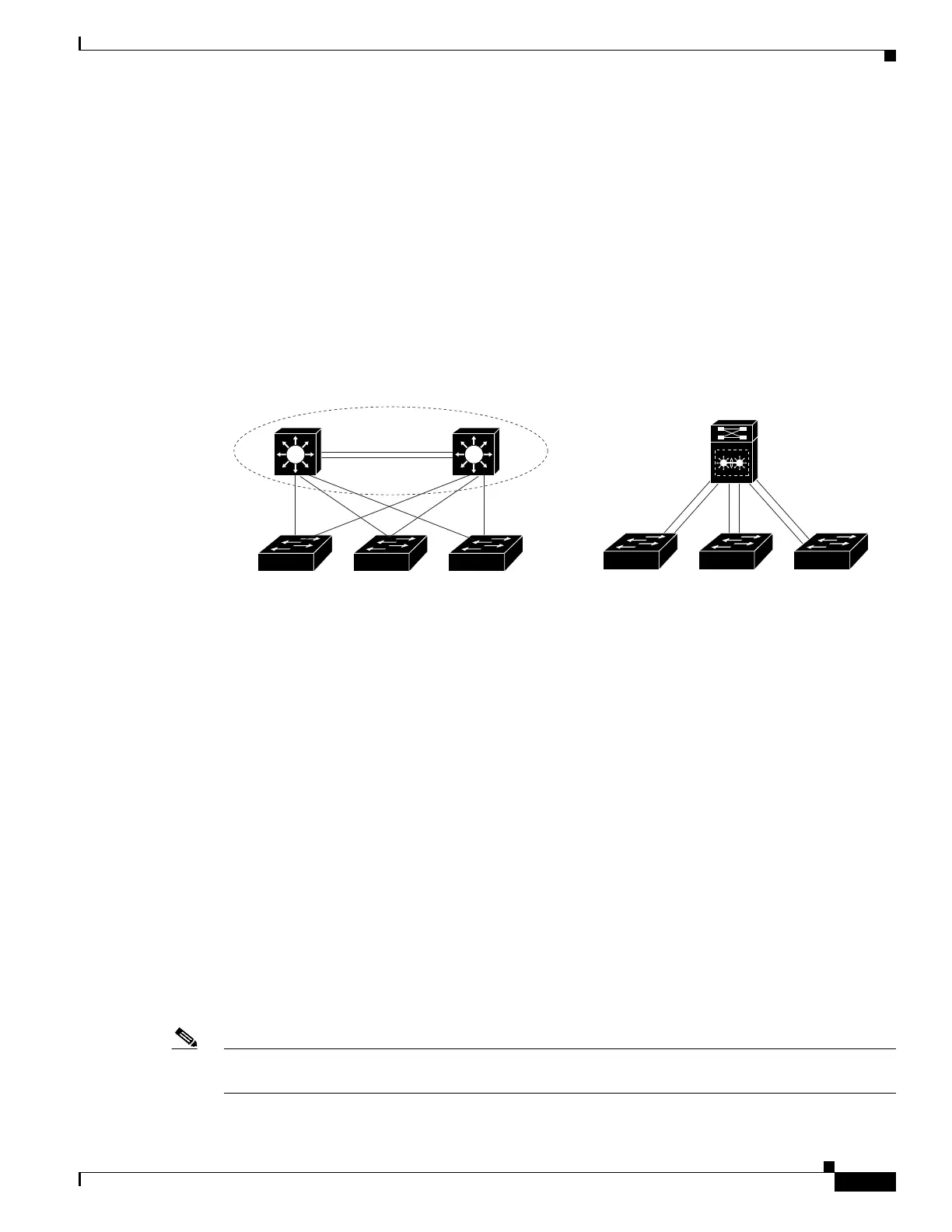
A VSS combines a pair of switches into a single network element. For example, a VSS in the distribution
layer of the network interacts with the access and core networks as if it were a single switch. See
Figure 5-2.
An access switch connects to both switches of the VSS using one logical port channel. The VSS manages
redundancy and load balancing on the port channel. This capability enables a loop-free Layer 2 network
topology. The VSS also simplifies the Layer 3 network topology by reducing the number of routing peers
in the network.
Figure 5-2 VSS in the Distribution Network
VSS Active and VSS Standby Switch
When you create or restart a VSS, the peer switches negotiate their roles. One switch becomes the VSS
Active switch, and the other switch becomes the VSS Standby switch.
The VSS Active controls the VSS, running the Layer 2 and Layer 3 control protocols for the switching
modules on both switches. The VSS Active switch also provides management functions for the VSS,
such as module online insertion and removal (OIR) and the console interface.
The VSS Active and VSS Standby switches perform packet forwarding for ingress data traffic on their
locally hosted interfaces. However, the VSS Standby switch sends all control traffic to the VSS Active
switch for processing.
Virtual Switch Link
For the two switches of the VSS to act as one network element, they need to share control information
and data traffic.
The virtual switch link (VSL) is a special link that carries control and data traffic between the two
switches of a VSS, as shown in Figure 5-3. The VSL is implemented as an EtherChannel with up to eight
links. The VSL gives control and management traffic higher priority than data traffic so that control and
management messages are never discarded. Data traffic is load balanced among the VSL links by the
EtherChannel load-balancing algorithm.
Note EtherChannel load balancing method is a global configuration; VSL observes that method of load
balancing.
181321
Virtual Distribution Switch Virtual Distribution Switch
Access
Access
Physical view Logical view

 Loading...


