83-5
Catalyst 4500 Series Switch, Cisco IOS Software Configuration Guide - Cisco IOS XE 3.9.xE and IOS 15.2(5)Ex
Chapter 83 Configuring Easy Virtual Network
About Easy Virtual Network
Edge Interfaces and EVN Trunk Interfaces
User devices are connected to a Layer 2 switch port, which is assigned to a VLAN. A VLAN can be
thought of as a Layer 2 VPN. Customers will group all of the devices that need to be supported in a
common Layer 3 VPN in a single VLAN. The point where data traffic is handed off between a VLAN
and VRF is called an edge interface.
An edge interface connects a user device to the EVN and in effect defines the boundary of the EVN.
Edge interfaces connect end devices such as hosts and servers that are not VRF-aware. Traffic carried
over the edge interface is untagged. The edge interface classifies which EVN the received traffic belongs
to. Each edge interface is configured to belong to only one EVN.
An EVN trunk interface connects VRF-aware devices together and provides the core with a means to
transport traffic for multiple EVNs. Trunk interfaces carry tagged traffic. The tag is used to de-multiplex
the packet into the corresponding EVN. A trunk interface has one subinterface for each EVN.
The vnet trunk command is used to define an interface as an EVN trunk interface.
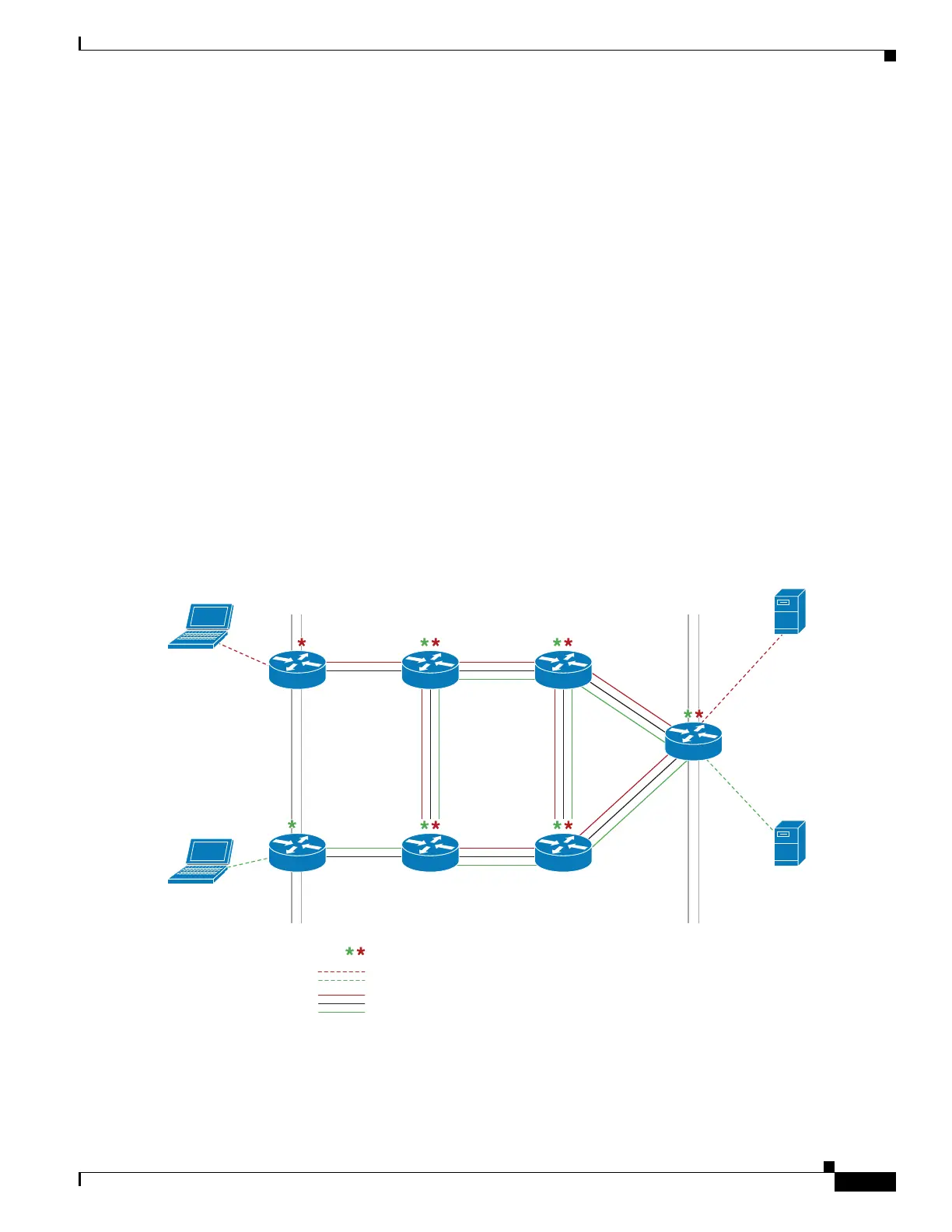
An EVN interface uses two types of interfaces: edge interfaces and trunk interfaces. An interface can be
an edge or trunk interface, but not both. Figure 3 illustrates devices A and D, which have edge interfaces
that belong to VRF Red. Devices D and E have edge interfaces that belong to VRF Green.
Devices B, C, D, F, and G have trunk interfaces that make up the EVN core. These five devices have
interfaces that belong to both VRF Red and VRF Green.
Figure 83-3 EVN Edge and EVN Trunk Interfaces
Edge interface Edge interfaceTr unk interfaces make up the VRF core
277895
Each asterisk indicates VRF definition
Each dashed line indicates edge interface
Parallel solid lines group indicates trunk interface
Device A Device B Device C
Device E Device F Device G
Device D
 Loading...


