83-9
Catalyst 4500 Series Switch, Cisco IOS Software Configuration Guide - Cisco IOS XE 3.9.xE and IOS 15.2(5)Ex
Chapter 83 Configuring Easy Virtual Network
About Easy Virtual Network
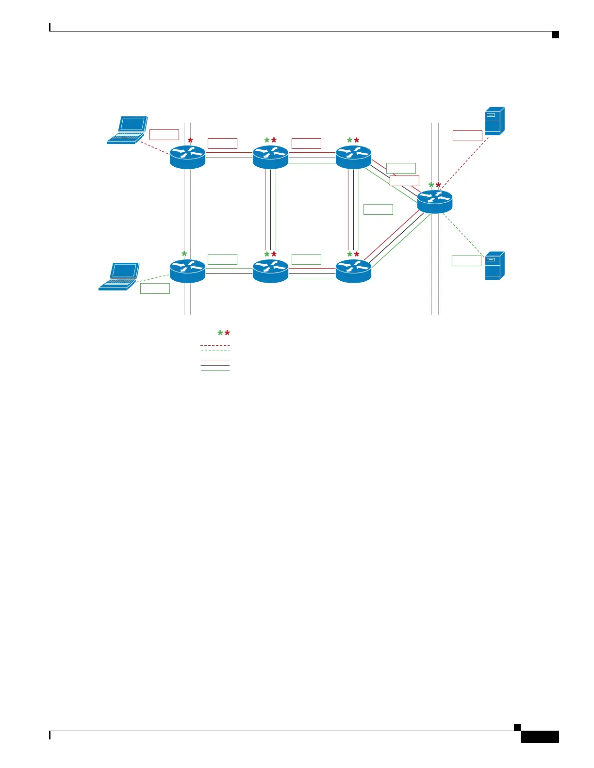
Figure 83-5 Packet Flow in a Virtual Network
The packet flow from Laptop 1 to Server 1 in VRF red occurs as follows:
1. Laptop 1 send an untagged packet to Server 1.
2. Device A receives the packet over an edge interface, which is associated with VRF red.
a. Device A does route lookup in VRF red and sees that the next hop is Device B through a trunk
interface.
b. Device A encapsulates the packet with VRF red’s tag (101) and sends it over the trunk interface.
3. Device B receives the packet over a trunk interface. Seeing virtual network tag 101, Device B
identifies that the packet belongs to VRF red.
a. Device B does route lookup in VRF red and sees that the next hop is Device C through a trunk
interface.
b. Device B encapsulates the packet with VRF red’s tag (101) and sends it over the trunk interface.
4. Device C receives the packet over a trunk interface. Using virtual network tag 101, Device C
identifies that the packet belongs to VRF red.
a. Device C does route lookup in VRF red and sees that the next hop is Device D through a trunk
interface.
b. Device C encapsulates the packet with VRF red’s tag (101) and sends it over the trunk interface.
5. Device D receives the packet over a trunk interface. Using virtual network tag 101, Device D
identifies that the packet belongs to VRF red.
a. Device D does route lookup in VRF red and sees that the next hop is through an edge interface.
b. Device D sends the untagged packet over the edge interface to Server 1.
6. Server 1 receives the untagged packet originated from Laptop 1.
Edge interface Edge interfaceTr unk interfaces make up the VRF core
277897
Each asterisk indicates VRF definition
Each dashed line indicates edge interface
Parallel solid lines group indicates trunk interface
Device A Device B Device C
Device E Device F Device G
Device D
Server 1
Laptop 1
Laptop 2
Server 1
101 101
102 102
102
102
101
 Loading...


