5-35
Catalyst 4500 Series Switch, Cisco IOS Software Configuration Guide - Cisco IOS XE 3.9.xE and IOS 15.2(5)Ex
Chapter 5 Configuring Virtual Switching Systems
Configuring a VSS
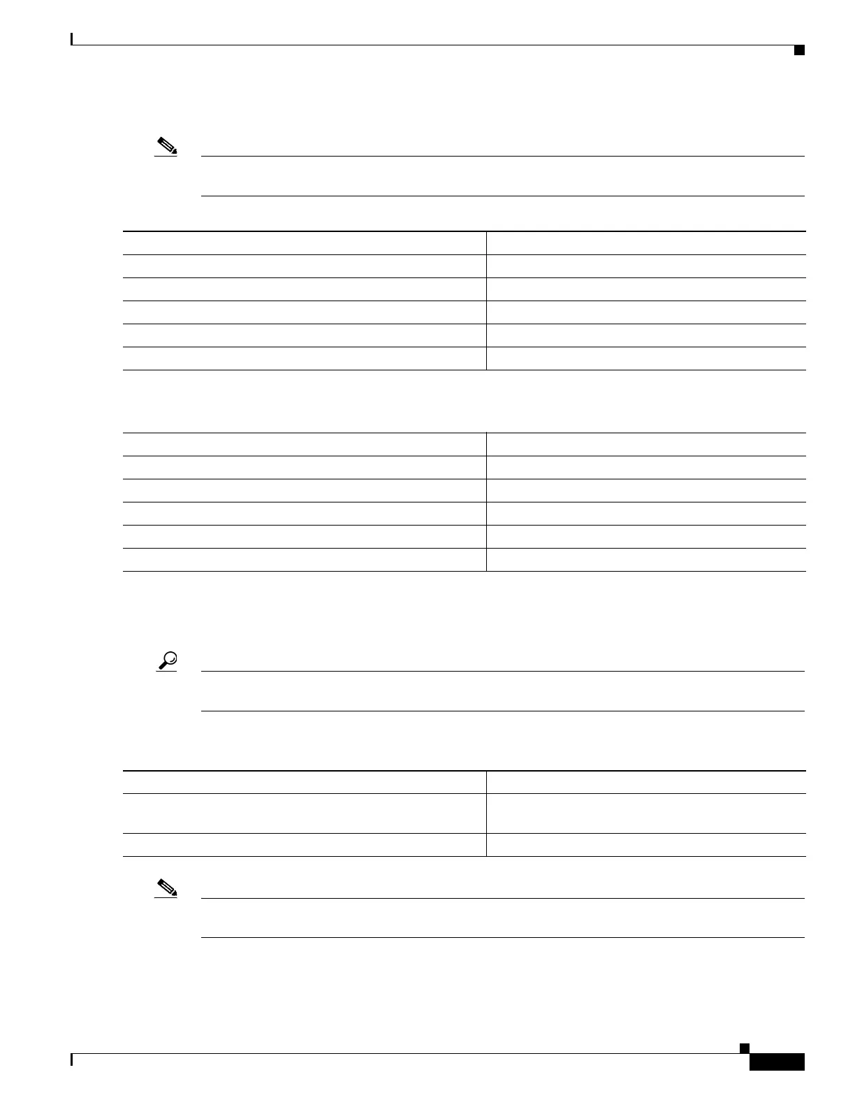
To configure the VSL port channels, perform this task on Switch 1:
Note The port channels 10 and 20 mentioned in the configuration steps below are exemplary only. You can
configure any port channel number from 1-64 for VSL port channel.
Perform the following task on Switch 2:
You must add the VSL physical ports to the port channel. In the following example, interfaces 10-Gigabit
Ethernet 3/1 and 3/2 on Switch 1 are connected to interfaces 10-Gigabit Ethernet 5/2 and 5/3 on
Switch 2.
Tip For line redundancy, we recommend configuring at least two ports per switch for the VSL. For module
redundancy, the two ports can be on different switching modules in each chassis.
To configure the VSL ports, perform this task on Switch 1:
Note 1G ports, which are converted from 10G ports using a connector, are not supported for VSL. This
impacts Sup7-E and Sup7L-E ports.
Command Purpose
Step 1
Switch-1(config)# interface port-channel 10
Configures port channel 10 on Switch 1.
Step 2
Switch-1(config)# switchport
Convert to a Layer 2 port.
Step 3
Switch-1(config-if)# switch virtual link 1
Associates Switch 1 as owner of port channel 10.
Step 4
Switch-1(config-if)# no shutdown
Activates the port channel.
Step 5
Switch-1(config-if)# exit
Exits interface configuration.
Command Purpose
Step 1
Switch-2(config)# interface port-channel 20
Configures port channel 20 on Switch 2.
Step 2
Switch-1(config)# switchport
Convert to a Layer 2 port.
Step 3
Switch-2(config-if)# switch virtual link 2
Associates Switch 2 as owner of port channel 20.
Step 4
Switch-2(config-if)# no shutdown
Activates the port channel.
Step 5
Switch-2(config-if)# exit
Exits interface configuration mode.
Command Purpose
Step 1
Switch-1(config)# interface range
tengigabitethernet 3/1-2
Enters configuration mode for interface range
tengigabitethernet 3/1-2 on Switch 1.
Step 2
Switch-1(config-if)# channel-group 10 mode on
Adds this interface to channel group 10.

 Loading...


