7-22
Catalyst 4500 Series Switch, Cisco IOS Software Configuration Guide - Cisco IOS XE 3.9.0E and IOS 15.2(5)E
Chapter 7 Configuring the Cisco IOS In-Service Software Upgrade Process
Performing the ISSU Process
This example shows how to start the ISSU process, boot the standby supervisor engine in the Standby
Hot state, and load the standby supervisor engine slot (2) with the new image:
Switch> enable
Switch# issu loadversion 1 bootflash:new_image 2 slavebootflash:new_image
Switch# show issu state detail
Slot = 1
RP State = Active
ISSU State = Load Version
Boot Variable = bootflash:old_image,12
Operating Mode = Stateful Switchover
Primary Version = bootflash:old_image
Secondary Version = bootflash:new_image
Current Version = bootflash:old_image
Slot = 2
RP State = Standby
ISSU State = Load Version
Boot Variable = bootflash:new_image,12;bootflash:old_image,12
Operating Mode = Stateful Switchover
Primary Version = bootflash:old_image
Secondary Version = bootflash:new_image
Current Version = bootflash:new_image
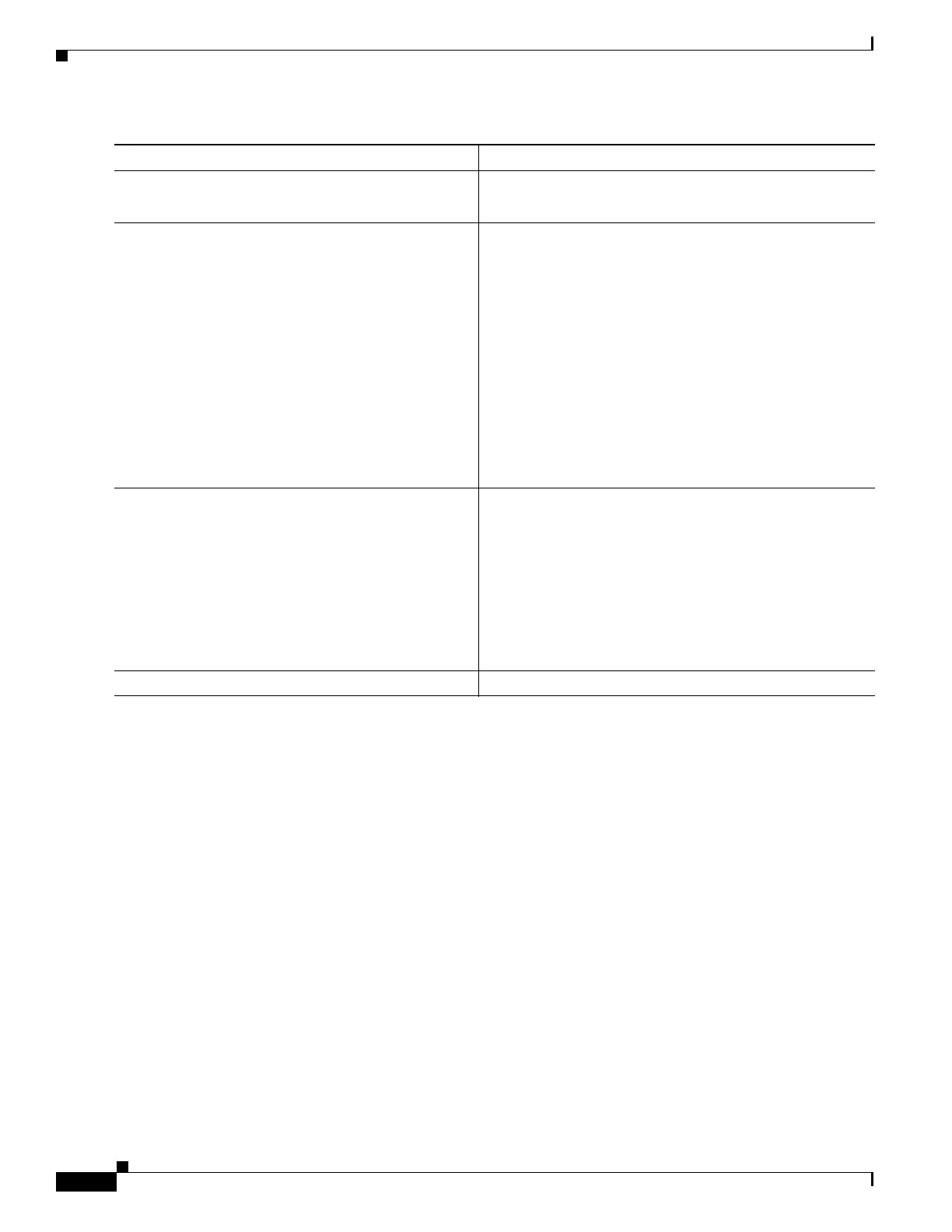
Command or Action Purpose
Step 1
Switch> enable
Enables privileged EXEC mode.
• Enter your password if prompted.
Step 2
Switch# issu loadversion active-slot
active-image-new standby-slot standby-image-new
[forced]
Starts the ISSU process and (optionally) overrides the
automatic rollback when the new Cisco IOS software
version is detected to be incompatible.
It may take several seconds after the issu loadversion
command is entered for Cisco IOS software to load onto the
standby supervisor engine and for the standby supervisor
engine to transition to SSO mode. This causes the standby
supervisor engine to reload with the new image.
If you use the forced option, the standby supervisor engine
is booted with the new image. After the image is loaded on
the standby supervisor engine, if the image is incompatible,
the system is forced to the RPR mode. Otherwise the system
continues in the SSO mode.
Step 3
Switch# show issu state [detail]
Displays the state of the during the ISSU process. At this
point in the ISSU process, use this command to check that
the standby supervisor engine is loaded and is in SSO mode.
It may take several seconds after entering the
issu loadversion command for Cisco IOS software to load
onto the standby supervisor engine and the standby
supervisor engine to transition to SSO mode. If you enter
the show issu state command too quickly, you may not see
the information you need.
Step 4
Switch# show redundancy [states]
Displays redundancy facility state information.

 Loading...


