14-18
Catalyst 4500 Series Switch, Cisco IOS Software Configuration Guide - Cisco IOS XE 3.9.xE and IOS 15.2(5)Ex
Chapter 14 Environmental Monitoring and Power Management
Power Management
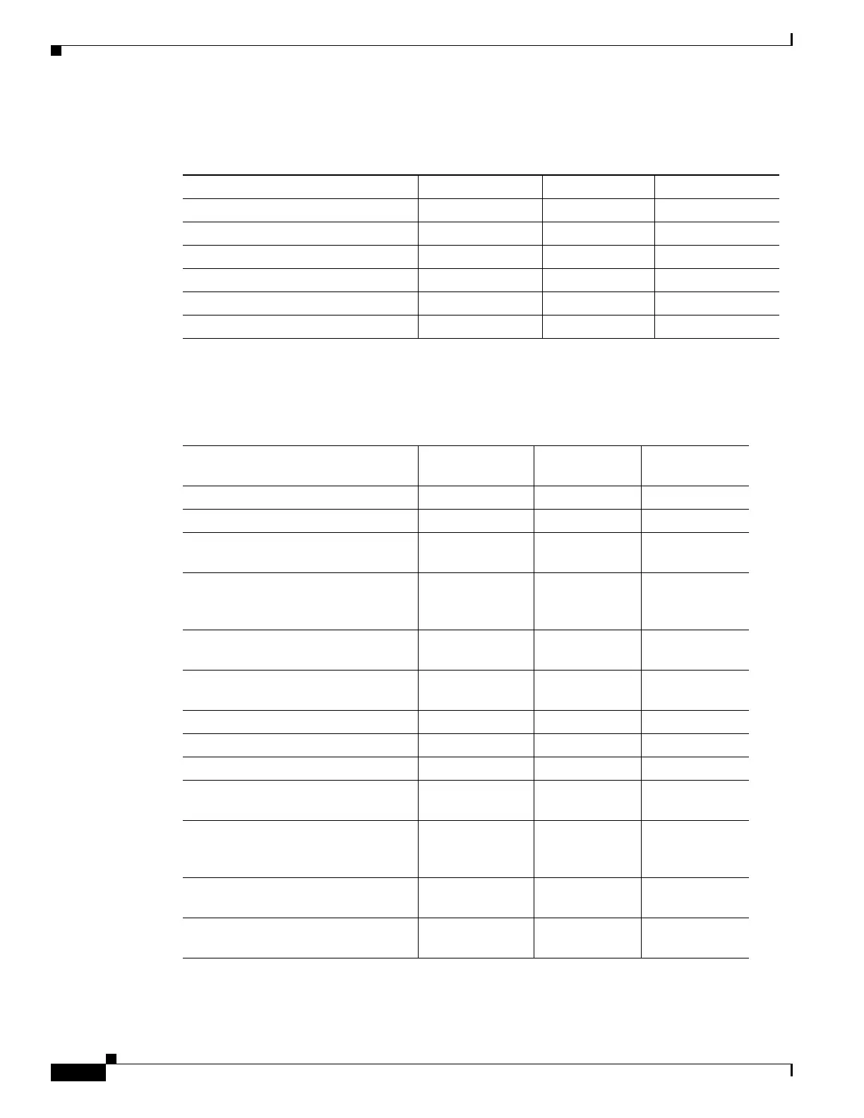
Table 14-10 illustrates how the 9000 W AC power supply is evaluated in redundant mode.
Table 14-11 illustrates how the 9000 W AC power supply is evaluated in combined mode.
Table 14-10 Power Output in Redundant Mode for the 9000 W AC Power Supply
Power Supply 12V (data) (W) -50V (PoE) (W)
1
Total Power (W)
1. Power supply output drawings should not exceed the total power.
110VAC 960 1000 1100
110VAC + 110 VAC 1460 2000 2200
110VAC + 110 V AC+ 110VAC 1460 2500 3300
220VAC 1460 2500 3000
220VAC + 220VAC 1960 5000 6000
220VAC + 220VAC + 220VAC 1960 7500 9000
Table 14-11 Power Output in Combined Mode for the 9000 W AC Power Supply
Power Supply 12V (data) (W) -50V (PoE) (W)
1
Total Power
(W)
1. Power supply output drawings should not exceed the total power.
Both sides at 110 VAC 1594 1660 1790
Both sides at 110VAC + 110VAC 2424 3320 3610
Both sides at 110VAC + 110VAC +
110VAC
2424 4150 5420
One side at 110VAC + 110VAC +
110VAC, the other at 110VAC +
110VAC
2020 3458 4510
One side at 110VAC + 110VAC +
110VAC, the other at 110VAC
1615 2767 3600
One side at 110VAC + 110VAC, the
other at 110VAC
1818 2490 2700
Both sides at 220VAC 2424 4150 4930
Both sides at 220VAC + 220VAC 3763 8300 10140
Both sides at 220VAC + 220VAC +
220VAC
3763 14400 17210
One side at 220VAC + 220VAC +
220VAC, the other at 220VAC +
220VAC
2940 11250 13430
One side at 220VAC + 220VAC +
220VAC, the other at 220VAC
2169 8300 9900
One side at 220VAC + 220VAC, the
other at 220VAC
2646 6225 7410

 Loading...


