35-4
Catalyst 4500 Series Switch, Cisco IOS Software Configuration Guide - Cisco IOS XE 3.9.xE and IOS 15.2(5)Ex
Chapter 35 Configuring Layer 3 Interfaces
About Layer 3 Interfaces
• Input multicast
• Output unicast
• Output multicast
For each counter type, both the number of packets and the total number of bytes received or transmitted
are counted. You can collect these statistics uniquely for IPv4 and IPv6 traffic.
Because the total number of supported Layer 3 interfaces exceeds the number of counters supported by
hardware, all Layer 3 interfaces might not have counters. You assign counters to Layer 3 interfaces; the
default configuration for a Layer 3 interface has no counters.
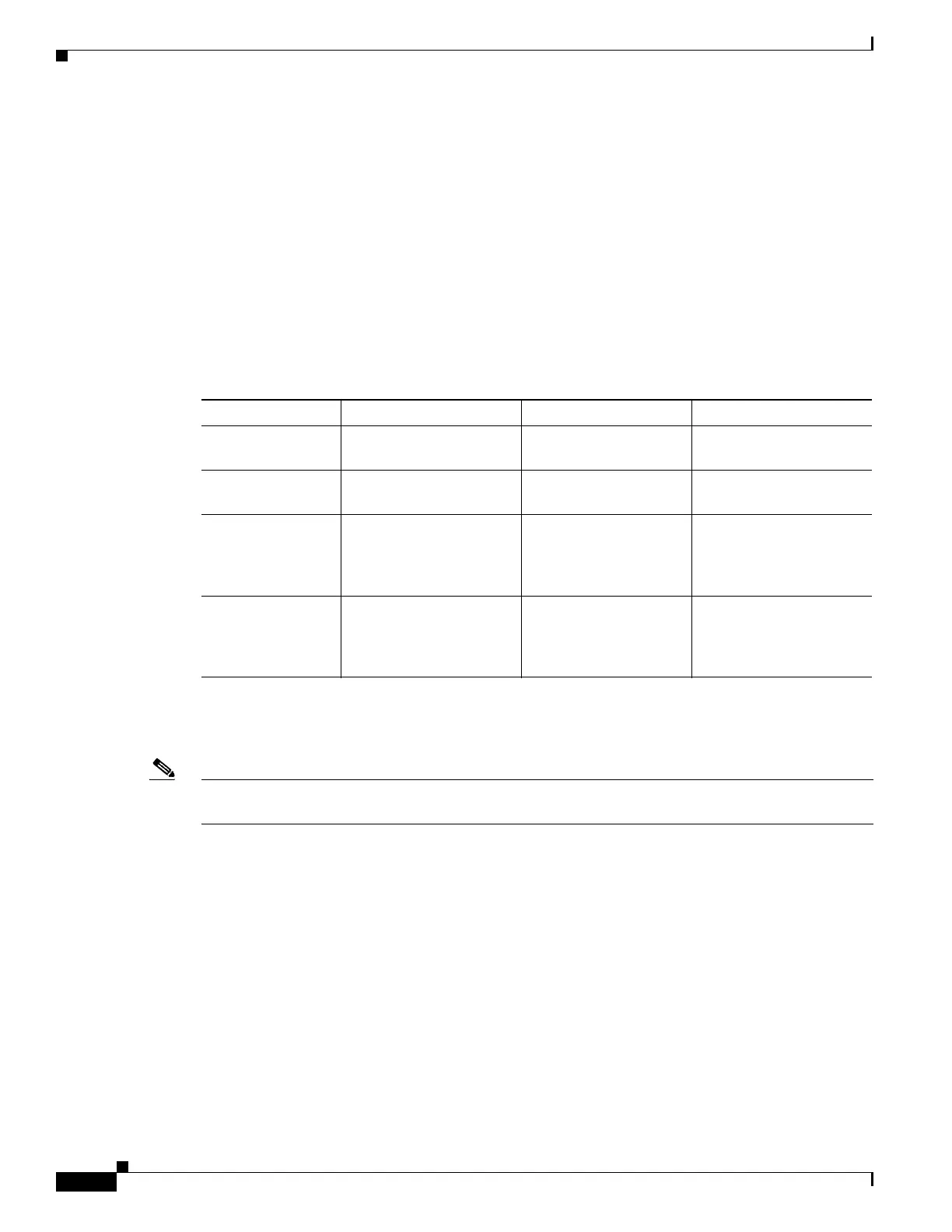
You can configure collection statistics at an interface level in one of the four ways (see Table 35-1). The
maximum number of interfaces applied to the configuration depends on the collection mode.
When mixing these configured modes, the rule is as follows:
(number of v4/v6/v4v6combined interfaces) + 2*(number of v4v6separate interfaces) <= 4092
Note To enable Layer 3 interface counters, you need to enter the counter command in interface mode. For
instructions, see the “Configuring Layer 3 Interface Counters” section on page 35-11.
The hardware counters are displayed in the output of the show interface command, as shown in the
following example. Counter fields that are updated when the counter configuration is present are
highlighted.
Switch# show interface gi3/1
GigabitEthernet3/1 is up, line protocol is up (connected)
Hardware is Gigabit Ethernet Port, address is 001f.9e9e.f43f (bia 001f.9e9e.f43f)
Internet address is 10.10.10.2/24
MTU 1500 bytes, BW 1000000 Kbit, DLY 10 usec,
reliability 255/255, txload 1/255, rxload 1/255
Encapsulation ARPA, loopback not set
Keepalive set (10 sec)
Full-duplex, 1000Mb/s, link type is auto, media type is 10/100/1000-TX
input flow-control is on, output flow-control is on
Auto-MDIX on (operational: on)
ARP type: ARPA, ARP Timeout 04:00:00
Last input never, output never, output hang never
Table 35-1 Configuring Statistics Collection Node
Counter Mode Configuration CLI Function Maximum
IPv4 only counter ipv4 Only IPv4 statistics are
collected.
4092
IPv6 only counter ipv6 Only IPv6 statistics are
collected.
4092
IPv4 and IPv6
combined
counter Both IPv4 and IPv6
statistics are collected
but are displayed only as
a sum.
4092
IPv4 and IPv6
separate
counter ipv4 ipv6 separate Both IPv4 and IPv6
statistics are collected
and can be displayed
individually.
2046

 Loading...


