1. INTRODUCTION
1
1. INTRODUCTION
Thank you for purchasing this LEADER instrument. To use this instrument safely, read this
instruction manual thoroughly, and make sure that you know how to use the instrument
properly.
If some point about the operation of this instrument is still unclear after you have read this
instruction manual, refer to the contact information on the back cover of the manual to contact
LEADER, or contact your local LEADER agent.
After you have finished reading this manual, keep it in a convenient place so that you can refer
to it when necessary.
1.1 Scope of Warranty
This LEADER instrument has been manufactured under the strictest quality control guidelines.
LEADER shall not be obligated to furnish the following free services during the warranty
period.
1. Repair of malfunction or damages resulting from fire, natural calamity, or improper
voltage applied by the user.
2. Repair of a product that has been improperly repaired, adjusted, or modified by personnel
other than a factory-trained LEADER representative.
3. Repair of malfunctions or damages resulting from improper use.
4. Repair of malfunctions caused by devices other than this instrument.
5. Repair of malfunctions or damages without the presentation of a proof of purchase or
receipt bill for the instrument.
This Warranty is valid only in Japan.
1.2 Operating Precautions
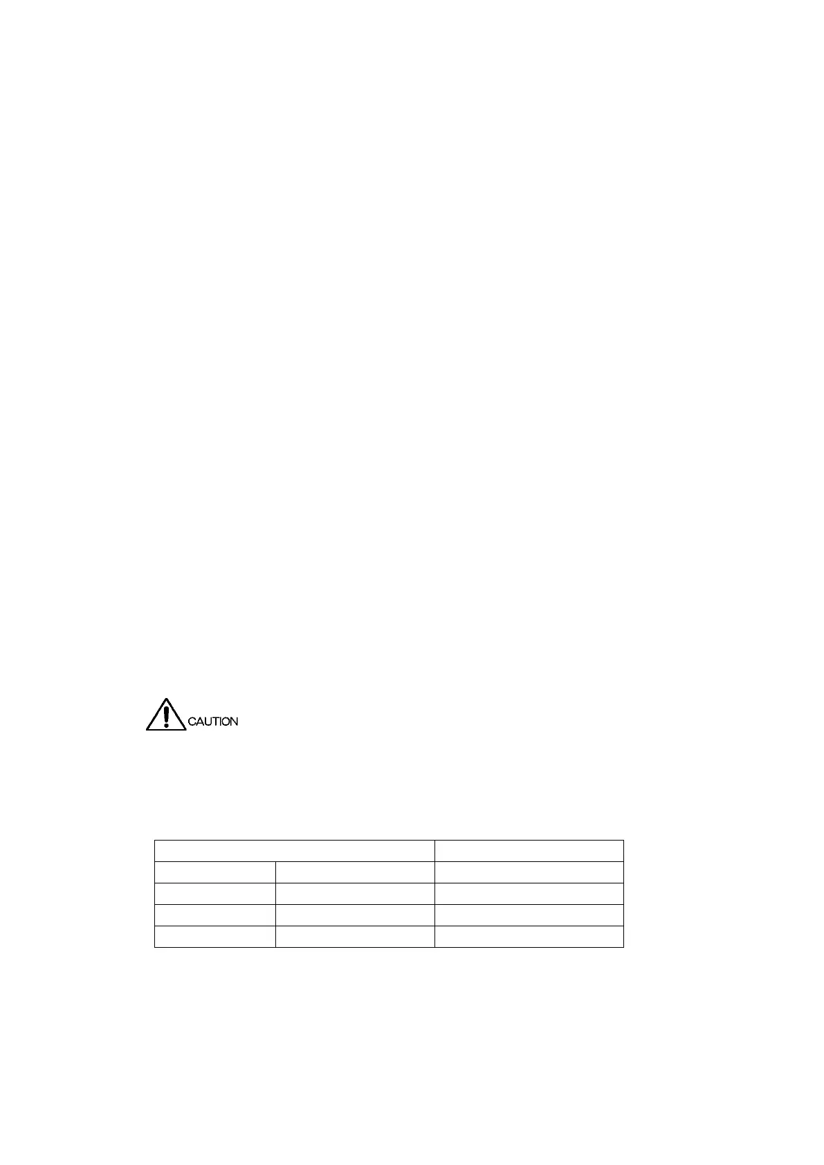
1.2.1 Maximum Allowable Input Voltage
The maximum signal voltage that can be applied to the input connectors is indicated below.
Do not apply excessive voltage to the connectors. Doing so may damage the device or lead
to injury.
Table 1-1 Maximum allowable input voltage