7. SYSTEM SETTINGS
132
7.1.5 Configuring the SDI Output Connectors
Use Output on the SDI OUT tab to configure the SDI OUTPUT connectors on the rear panel.
SYS → F•1 SIGNAL IN OUT → F•2 PREV TAB or F•3 NEXT TAB →
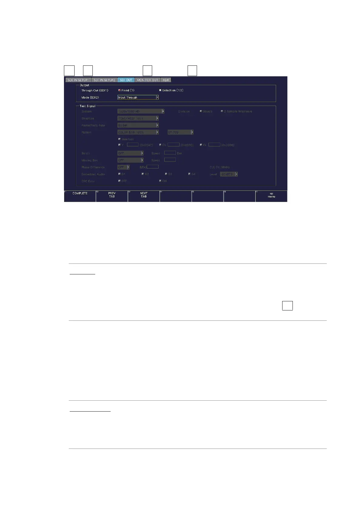
Figure 7-6 SDI OUT tab
• Through Out (SDI1)
Select the signal to output from SDI OUTPUT 1.
When SDI system setting is 2K SD/HD/3G-B-DL/3G-A and input signal is 6G-SDI, reclock
output is not possible.
Fixed (1): Transmits the reclocked version of the signal that has been received
by the SDI INPUT 1 connector.
Selection (1/2): Transmits the reclocked version of the signal that has been received
by the SDI INPUT 1 and 2 connectors.
To select the output channel, use the INPUT menu or F•6 INPUT
SELECT on each measurement screen.
• Mode (SDI2)
Select the signal output from SDI OUTPUT 2.
If SER24 TSG is not installed, Test Signal cannot be selected.
On the LV5300/LV5300A and LV5350, you can select Monitor Out. If you select Monitor
Out, SDI OUTPUT 2 transmits the instrument’s screen for monitoring purposes. On the
MONITOR OUT tab, select the output format.
[See also] MONITOR OUT tab → 7.1.7, “Configuring the Monitor Output Connectors.”
Input Through: Transmits the reclocked version of the signal that has been received by
the SDI INPUT 2 connector.
This is not output when the input is 6G-SDI or 12G-SDI.
Test Signal: Transmits the pattern specified by Test Signal.
Monitor Out Outputs the instrument’s screen. (LV5300/LV5300A/LV5350)