16. Status Display
365
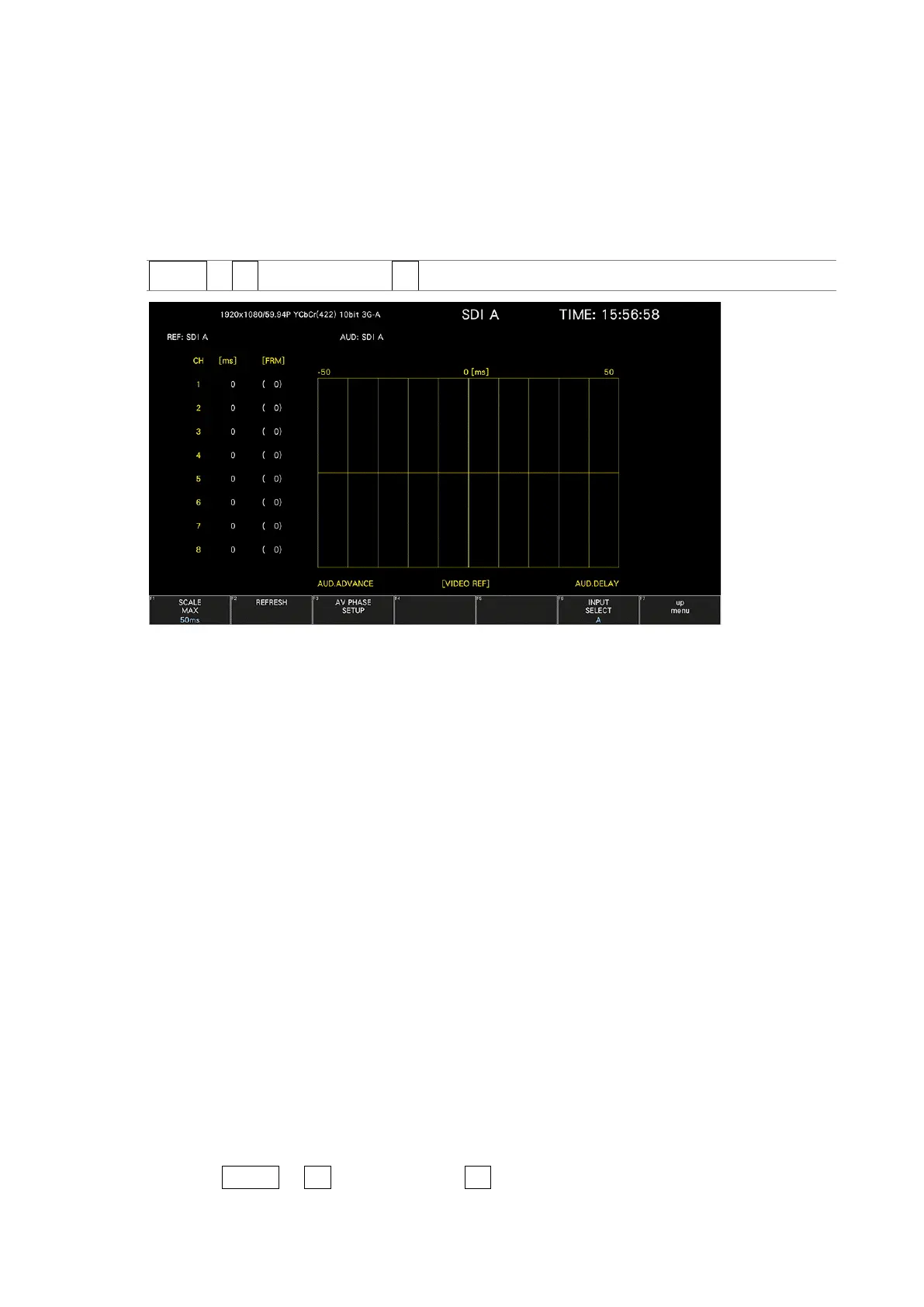
16.7 Setting the Lip Sync Measurement (SER20)
To show the lip sync measurement screen, follow the procedure below.
By combining a Leader signal generator that supports lip syncing with this instrument, you can
use the lip sync measurement screen to measure the offset between the video signal and the
audio signal that occurs in the transfer route.
Procedure
STATUS → F•2 SDI ANALYSIS → F•3 AV PHASE
Figure 16-13 Lip sync measurement screen
As an example, below is the procedure for when the LT4600A, LT4610 (with LT4610-SER02
and LT4610-SER24 installed according to the format), or LT4611 (with LT4610-SER22 installed
and LT4610-SER02 and LT4611-SER24 installed according to the format) is used for the signal
generator with a lip sync feature when the audio output is set to SDI embedded audio.
1. Turn the signal generator that supports lip syncing lip sync feature on.
• On the LT4600A
Select SDI SETTING→SDI→LIPSYNC to turn lip sync on. Select AES/EBU
SETTING→AES/EBU 1→LIPSYNC ENABLE to set the audio. For details, see the LT4600A
instruction manual.
• On the LT4610 or LT4611
Depending on the format, select ETC→LIPSYNC→SDI1+AES / SDI2 or 12G
OPTION→SDI 1 / 2 / 3 / 4→VIDEO→LIPSYNC to turn lip sync on. Then, select SDI→
SDI1 / 2→ AUDIO or 12G OPTION→SDI 1 / 2 / 3 / 4→AUDIO to set the audio. For
details, see the LT4610 or LT4611 instruction manual.
2. Send the signal generated from the signal generator that supports lip syncing SDI output
connector to the transfer route. Apply the signal received from the transfer route to the
SDI connector of this instrument.
3. The lip sync measurement screen is displayed.
Press STATUS → F•2 SDI ANALYSIS → F•3 AV PHASE.