5. BEFORE YOU BEGIN MEASURING
64
5.4.2 External Sync Signal Input
Figure 5-5 LV5300/LV5300A/LV5350 External sync signal input
connectors
Figure 5-6 LV7300 External sync signal input connectors
On the video-signal-waveform and vector displays, you can apply an external sync signal to
display waveforms. (*1) Apply an external sync signal to an external sync signal input
connector, and then press EXT. The instrument determines the sync signal format
automatically.
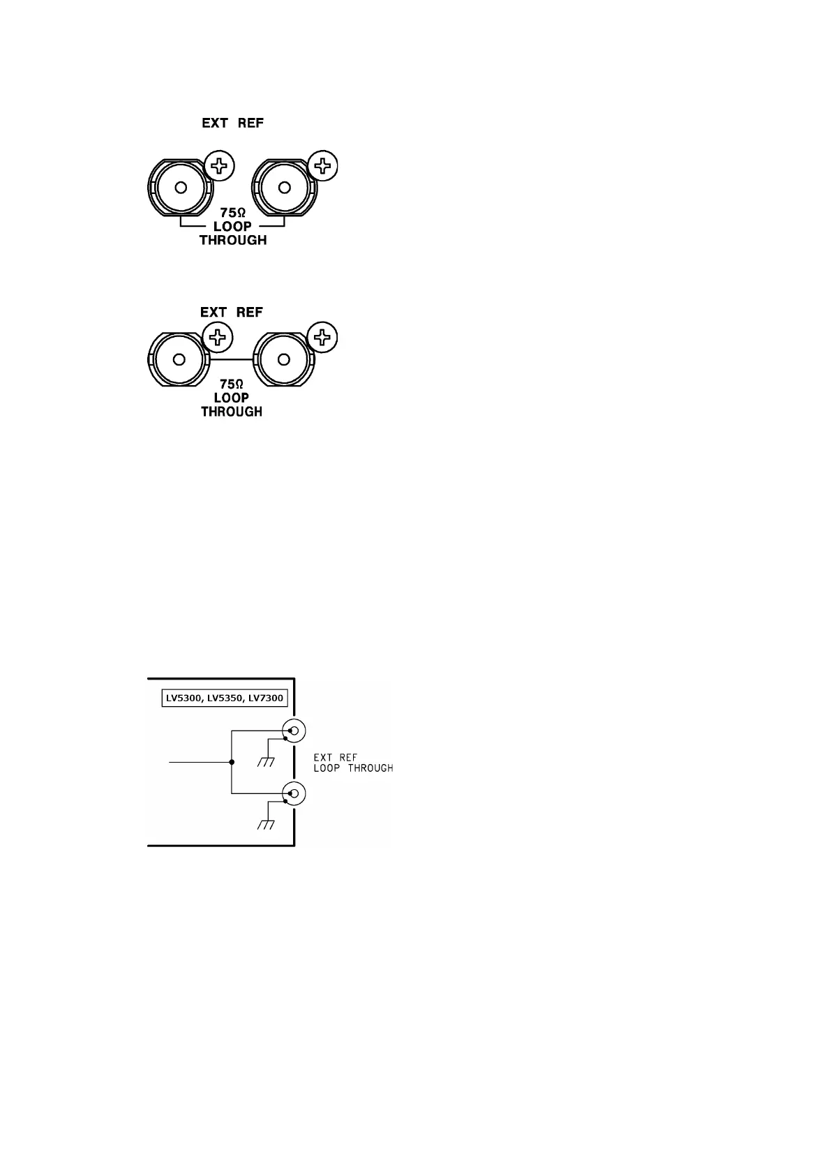
As shown in the figure below, the external sync signal input connectors are loop-through.
Apply the input signal to one of the two connectors, and terminate the other connector at
75 Ω, or connect it to another 75 Ω device. If you connect to another device, be sure to
terminate the device at the end of the chain at 75 Ω. Connect cables with a characteristic
impedance of 75 Ω.
Figure 5-7 Loop-through
*1 Waveform display using an external sync signal is not possible for the following formats.
• 3G’s 720/30P, 720/29.97P, 720/25P, 720/24P, 720/23.98P
• 3G(DL), 6G, 12G
• Frame frequency 48P, 47.95P