16. Status Display
361
16.6.1 Phase Difference Measurement Screen Description
• CURRENT PHASE
V PHASE: The phase difference is displayed in units of lines.
H PHASE: The phase difference is displayed in units of time and in units of pixels
or clocks. (*1)
TOTAL PHASE: The total of the V PHASE and H PHASE differences is displayed in
units of time.
*1 When the input signal is SD, the unit is clocks. Pixels are in units of the video's sampling
frequency. Clocks are in units of the parallel video's transmission clock frequency.
• REF
This displays the reference signal as shown below.
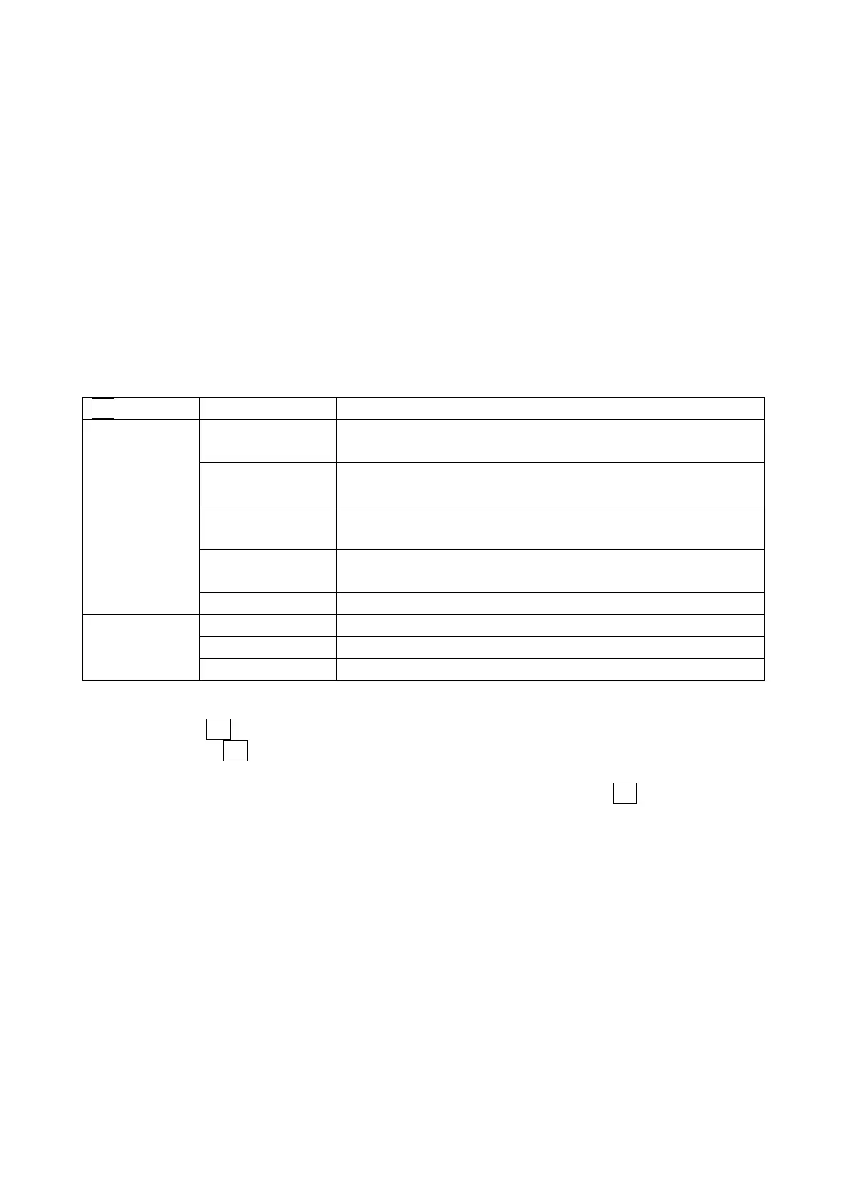
Table 16-8 REF indications
When the reference signal is BB and the phase difference is at the
default value
When the reference signal is BB and the phase difference is at the
user reference value
When the reference signal is HD3 and the phase difference is at the
default value
When the reference signal is HD3 and the phase difference is at the
user reference value
When no external sync signal is being applied
When the input signal is SD, HD, or 3G and the reference signal is A
When the input signal is 3G(DL)-4K and the reference signal is link 1
Indicates that the reference SDI signal is not being received.
• Setting the User-Defined Phase Difference Reference
When F•1 REF SELECT is set to EXT, you can set the current phase difference to zero by
pressing F•2 REF SET USER. You can change the reference to match the system that you
are using.
To reset the phase difference to its default value (see below), press F•3 REF SET
DEFAULT.