17. Eye Pattern Display (LV5300/LV5300A/LV7300-SER02)
397
17.1 Eye Pattern Display Description
• Automatic Measurement
On the eye pattern display, values such as the amplitude of the eye pattern and the jitter
are measured automatically and displayed. Measured values are normally displayed in white,
but they are displayed in yellow until they stabilize and in red if they exceed the values that
you have specified in the error setup. If automatic measurements cannot be performed due
to noise in the waveform or other reason, measured values are displayed as "----.” If this
occurs, use cursors to measure manually.
[See also] Reference 17.8, “Configuring Error Detection Settings”
The timing jitter and jitter measurement items show the values that were measured in jitter
display mode. The instrument uses the phase demodulator method.
Other measurement items show the measured values calculated from the eye pattern
waveform. Therefore, if the waveform degrades significantly, the difference between the
automatically measured values and the cursor-measured values may become large.
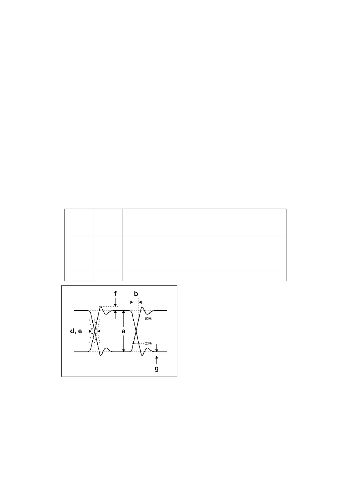
• Measurement items
The items that can be automatically measured are shown below.
Table 17-1 Measurement items