11. VECTOR DISPLAY
212
11.2.2 Selecting the Vector Mode (SER40)
When the SER40 is installed, you can select the vector mode, follow the procedure below.
The RGB VECTOR display consists of two factors.One is displayed the G and B components
of 100% color bar signal as unit vector on in the upper half of the measurement screen, and
the other is displayed the G and R components of the 100% color bar signal as the unit
vector in the lower half of the measurement screen. Each vertical axis shows the G + B and
-(G + R) of the 100% color bar signal, which is useful for monitoring the color conditions,
including the gamut errors.
The YCbCr VECTOR display shows the Cb signal as the horizontal axis and the Y signal as
the vertical axis in the upper half of the measurement screen, and the Cr signal as the
horizontal axis and the inverted Y signal as the vertical axis in the lower half of the
measurement screen. The luminance (Y signal) amplitude can be checked by the deviation
in the vertical axis direction from the center of each marker. The chrominance (Cb / Cr
signal) amplitude can be checked by the deviation in the horizontal axis direction from the
center of each marker.
Procedure
VECT → F•1 VECT INTEN/CONFIG → F•2 VECTOR MODE: VECTOR / RGB VECTOR / YCbCr
VECTOR
Settings
VECTOR: Shows vectors.
RGB VECTOR: Shows RGB vectors.
YCbCr VECTOR: Shows YCbCr vectors.
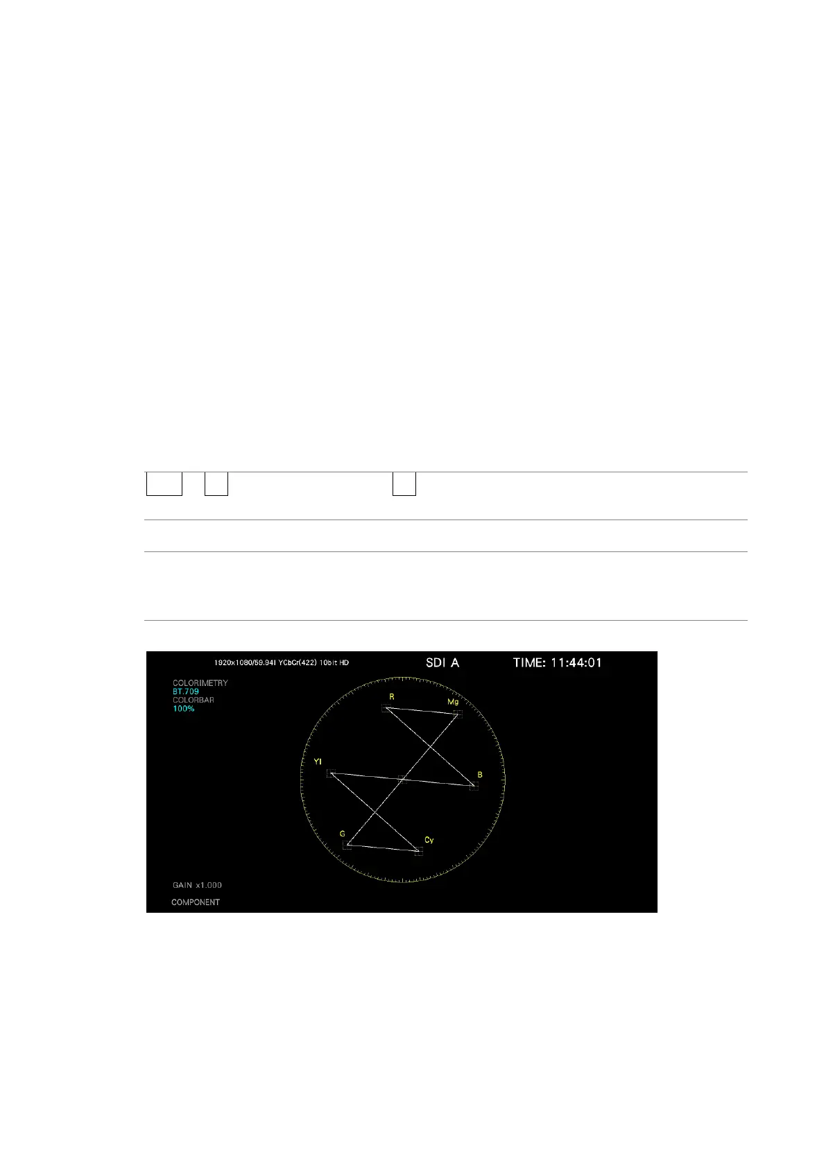
VECTOR MODE = VECTOR