13. Picture Screen
291
13.9.2 Setting the Line Selection Range
When F•1 LINE SELECT is set to ON and the input signal format is interlaced or segmented
frame, to set the line selection range, follow the procedure below.
Changing this setting will also change the selected line on the video-signal-waveform,
vector, and status (data dump) displays.
Procedure
PIC → F•5 LINE SELECT → F•2 FIELD: FIELD1 / FIELD2 / FRAME
Settings
FIELD1: A line from field 1 can be selected. (Example: 1 to 563)
FIELD2: A line from field 2 can be selected. (Example: 564 to 1125)
FRAME: All lines can be selected. (Example: 1 to 1125)
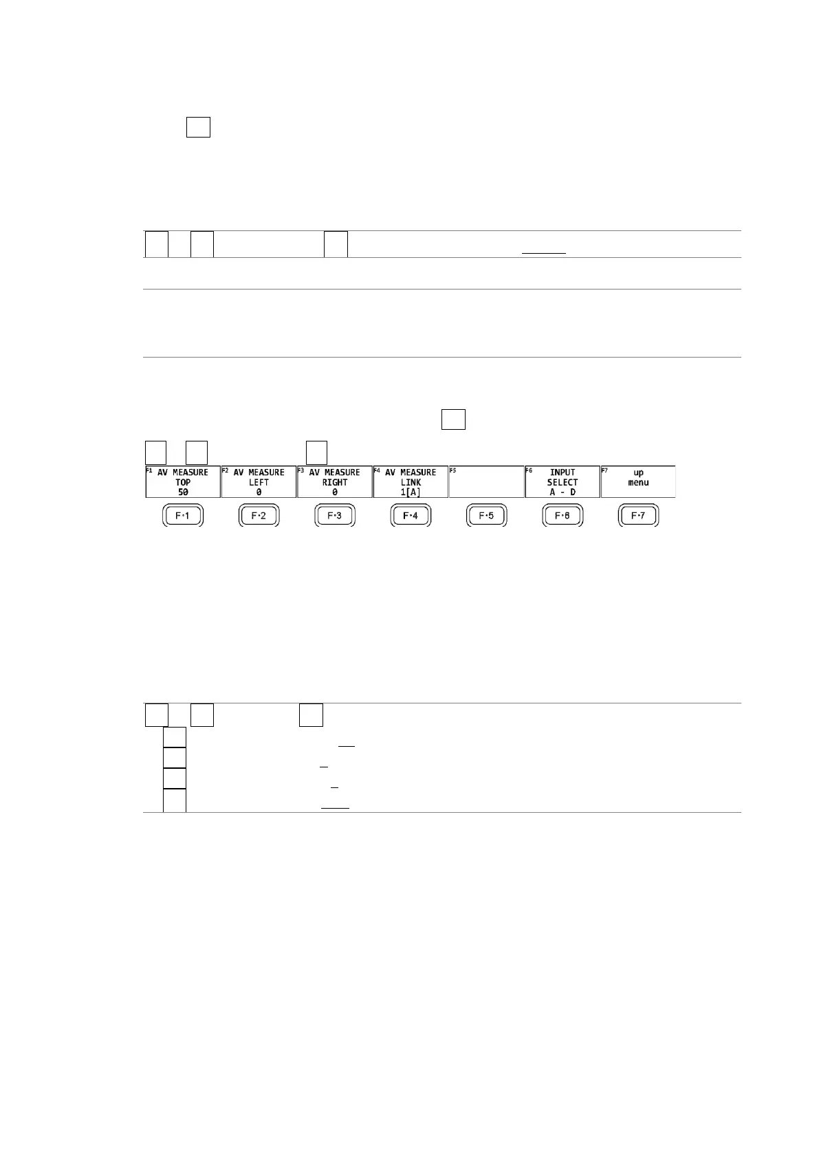
13.9.3 Setting the Lip Sync Measurement Range (SER20)
To set the lip sync measurement range, press F•3 AV PHASE on the LINE SELCT menu.
PIC → F•5 LINE SELECT → F•3 AV PHASE →
Figure 13-36 AV PHASE menu
To set the lip sync measurement range, follow the procedure below. Markers are displayed
at the specified lines.
You can also set these using AV PHASE SETUP of the STATUS menu, but here you can set
them while viewing the picture. For details on the settings, section 16.7.3, “Setting the
Measurement Range.”
Procedure
PIC → F•5 LINE SEL → F•3 AV PHASE
→ F•1 AV MEASURE TOP: 0 - 50 - 100
→ F•2 AV MEASURE LEFT: 0 - 99
→ F•3 AV MEASURE RIGHT: 0 - 99
→ F•4 AV MEASURE LINK: 1[A] / 2[B] / 3[C] / 4[D]