5. BEFORE YOU BEGIN MEASURING
62
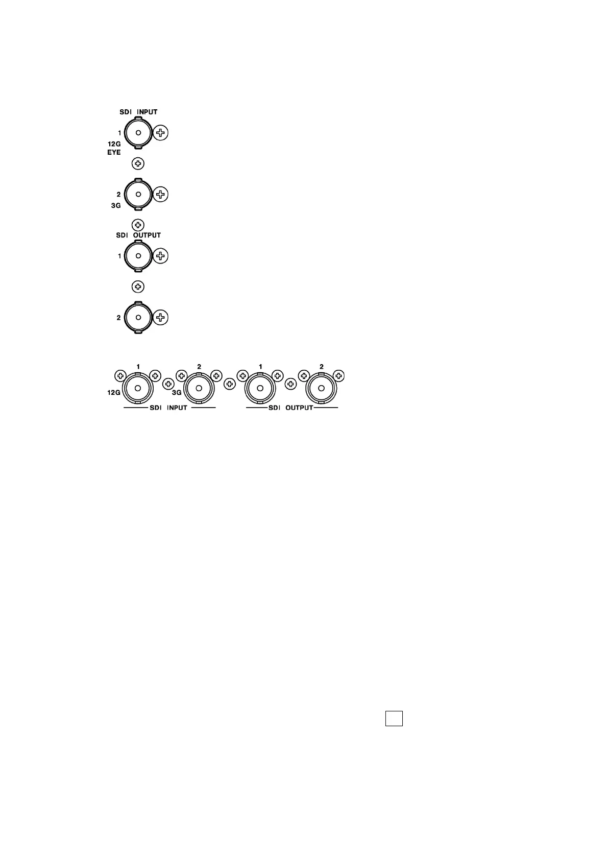
5.4 Signal I/O
5.4.1 SDI Signal I/O
Figure 5-3 LV5300/LV5300A/LV5350 SDI I/O connectors
* When an SER01 or SER02 is installed
Figure 5-4 LV7300 SDI I/O connectors
• SDI Signal Input SDI INPUT 1/2
Apply signals that are specified in section 3.3.1, “SDI Video Formats and Standards,” and
section 3.3.2, “SDI Audio Formats and Standards.”
Select the SDI System on the SDI IN SETUP1 tab of the SYS menu, and then apply signals
to SDI INPUT 1/2.
[See also] SDI IN SETUP1 tab → 7.1.1, “Configuring the SDI Input Connectors.”
• SDI Signal Output SDI OUTPUT 1/2
There are two SDI signal output settings: Through Out (SDI1) and Mode (SDI2). You can
set it on the SDI OUT tab of the SYS menu.
• Through Out (SDI1)
SDI OUTPUT 1 transmits reclocked signal of the signal received through SDI INPUT 1/2.
Use the signals for monitoring.
You can select whether to assign SDI OUTPUT 1 to SDI INPUT 1 or a channel that you
select, SDI INPUT 1 or 2, on the SDI OUT tab. If you select to use a channel that you
select, set the output channel using the INPUT menu or F•6 INPUT SELECT in the
appropriate measurement screen.