18. Remote Control
435
18.4 Tally Mode (SER27)
This section describes the control method when Mode on the SYS menu is set to Tally.
• Pinout
Table 18-6 Pinout
Channel A tally 1 display
Channel A tally 2 display
Channel A tally EX display
Channel B tally 1 display
Channel B tally 2 display
Channel B tally EX display
*1 Is (inputs) are all pulled up to +3.3 V but can also receive +5 V.
*2 Do not connect anything.
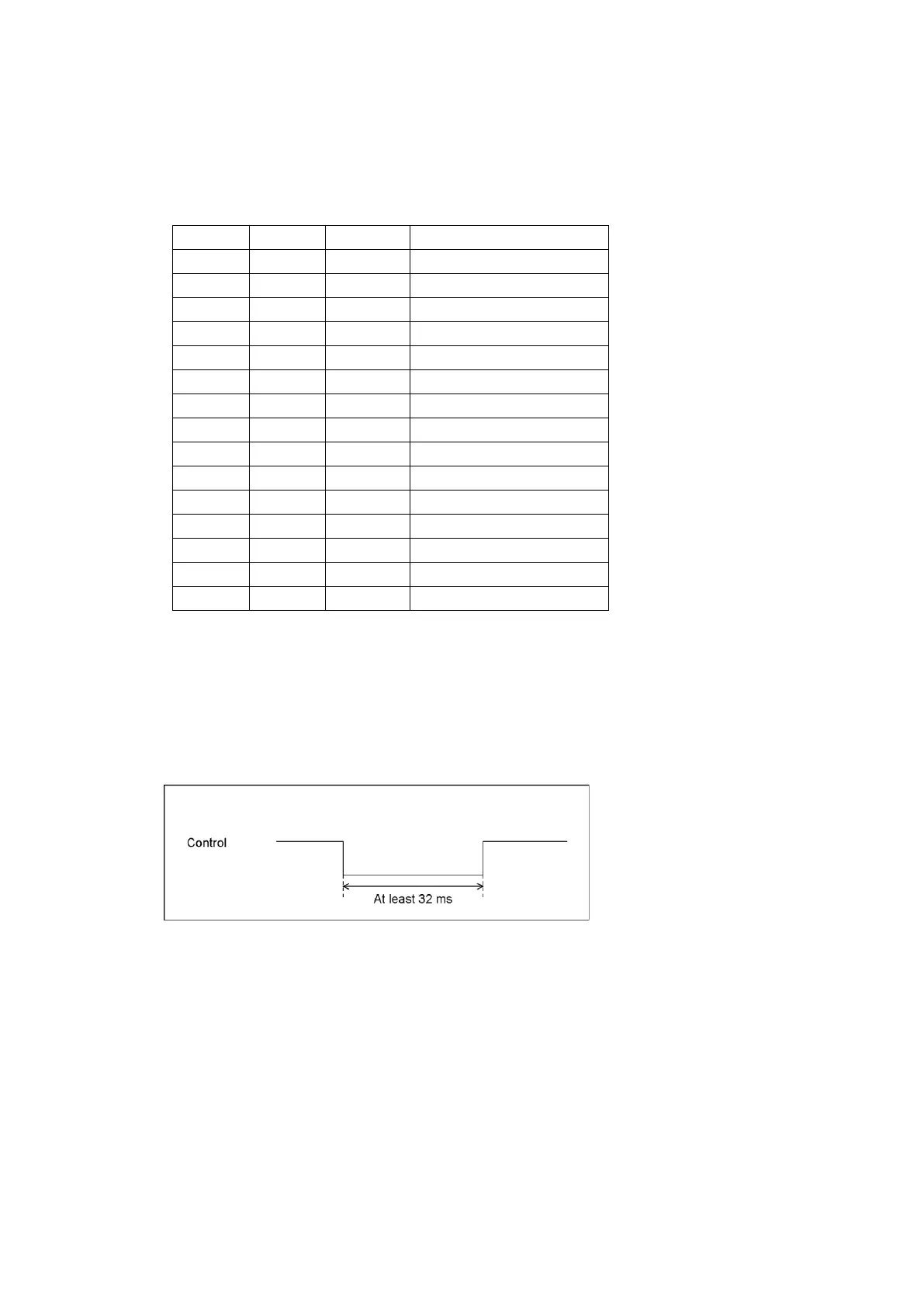
• Control
The input connectors respond to active-low signals. Tallies light at low level and turns off at
high level.
Set the low level period to at least 32 ms.
Figure 18-7 Control timing
• Alarm output
These are the same as Bit mode. See section 18.1, “Bit Mode.”