7. SYSTEM SETTINGS
137
7.1.7 Configuring the Monitor Output Connectors
On the LV5300/LV5300A and LV5350, use LCD/SDI on the MONITOR OUT tab to specify the
SDI signal (Monitor Out) transmitted from SDI OUTPUT 2 on the rear panel when Mode
(SDI2) is set to Monitor Out on the SDI OUT tab and configure the instrument’s LCD
settings.
On the LV7300, use LCD, TMDS, and SDI on the MONITOR OUT tab to configure the
MONITOR OUTPUT connectors on the rear panel.
SYS → F•1 SIGNAL IN OUT → F•2 PREV TAB or F•3 NEXT TAB →
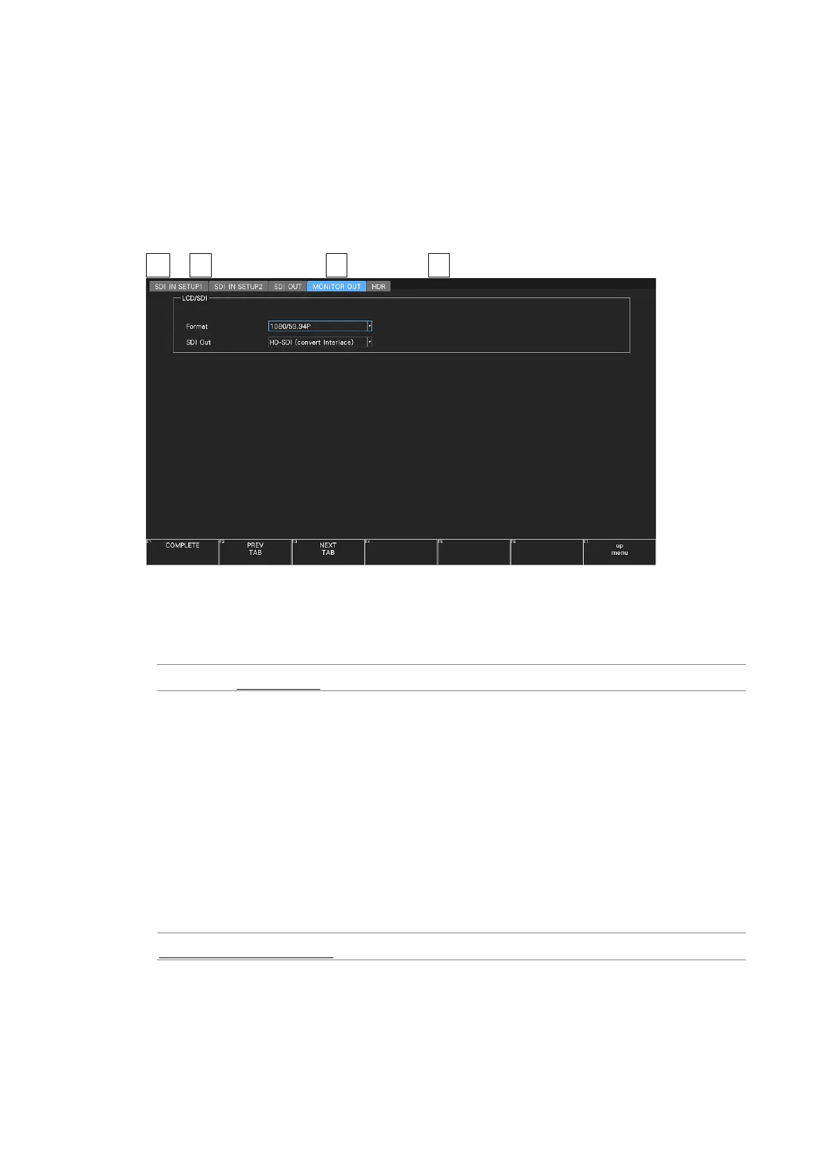
Figure 7-8 MONITOR OUT tab
• Format
Select the frame frequency of the output signal.
1080/60P / 1080/59.94P / 1080/50P / 1080/48P / 1080/47.95P
• SDI Out
Select the output format of the SDI signal.
If HD-SDI (convert Interlace) is selected, the frame frequency selected with Format is
switched and output in the following manner.
1080/60P → 1080/60I
1080/59.94P → 1080/59.94I
1080/50P → 1080/50I
1080/48P → 1080/24PsF (*1)
1080/47.95P → 1080/23.98PsF (*1)
*1 Equivalent to 48I when the SDI input is 48P.
HD-SDI (convert Interlace) / 3G-SDI Level-A / 3G-SDI Level-B