14. HDR Display (SER23)
307
To set the display colors, follow the procedure below. If you set REF at boundary of the SDR
area and HDR area, the SDR area can be displayed in monochrome and HDR area in color.
When Variable is set to on the HDR tab, you can set the REF value. If set to off, the default
value is used.
This setting is shared with REF.LEVEL [%] of the video signal waveform display.
UPPER or higher: Magenta
REF or higher, less than UPPER: Gradation from blue to red
LOWER or higher, less than REF: Monochrome
Less than LOWER: Black
Procedure
PIC → F•2 CINELITE/HDR → F•2 CINEZONE SETUP
→ F•2 UPPER [%]
→ F•3 LOWER [%]
→ F•4 REF [%]
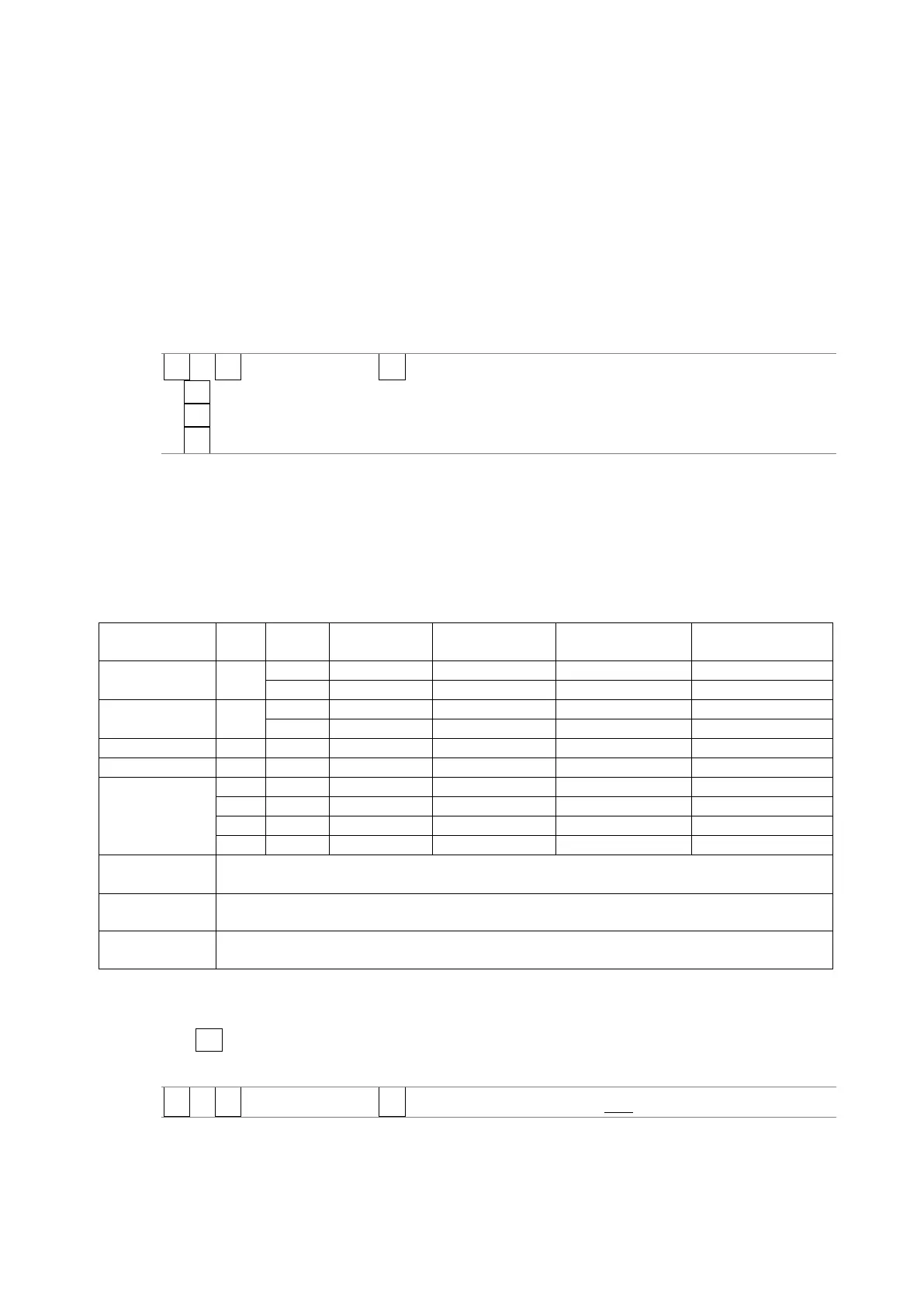
The values vary depending on the HDR tab settings as follows.
Set the values as percentages (0.0 to 100.0%) of the input video level.
If MAX FALL and MAX CLL displays are set to ON, HDR equivalent values are displayed in the
upper left corner of the screen.
[See also] MAX FALL and MAX CLL displays →14.4, “MAX FALL and MAX CLL Displays”
Figure 14-1 Display color values
Operates in OFF (SDR-TV), HLG, or PQ mode according to the payload ID information. When
the payload ID information is Unspecified, the instrument operates in S-Log3 mode.
Operates in OFF (SDR-TV), HLG, or PQ mode according to the payload ID information. When
the payload ID information is Unspecified, the instrument operates in C-Log mode.
Operates in OFF (SDR-TV), HLG, or PQ mode according to the payload ID information. When
the payload ID information is Unspecified, the instrument operates in Log-C mode.
14.3.4 Link Marker Display
Use F•4 CINELITE ADVANCE to configure the link marker display settings.
[See also] CINELITE ADVANCE → 13.6.8, “Displaying Link Markers”
PIC → F•2 CINELITE/HDR → F•4 CINELITE ADVANCE: ON / OFF