EasyManua.ls Logo

Leader LV5300A - Configuring SD Error Settings

Leader LV5300A
573 pages
Print Icon
To Next Page IconTo Next Page
To Previous Page IconTo Previous Page
Loading...
17. Eye Pattern Display (LV5300/LV5300A/LV7300-SER02)
412
17.8.5 Configuring SD Error Settings
Use the SD-SDI ERROR SETUP tab to configure error detection settings for SD signals.
You can set the threshold values when you set the error detection to ON. Measured values
given in SMPTE ST 259 are used as 100 %.
EYEF•1 EYE/JITTER INTEN/CONFIG F•5 ERROR SETUP → F•2 PREV TAB or F•3 NEXT TAB →
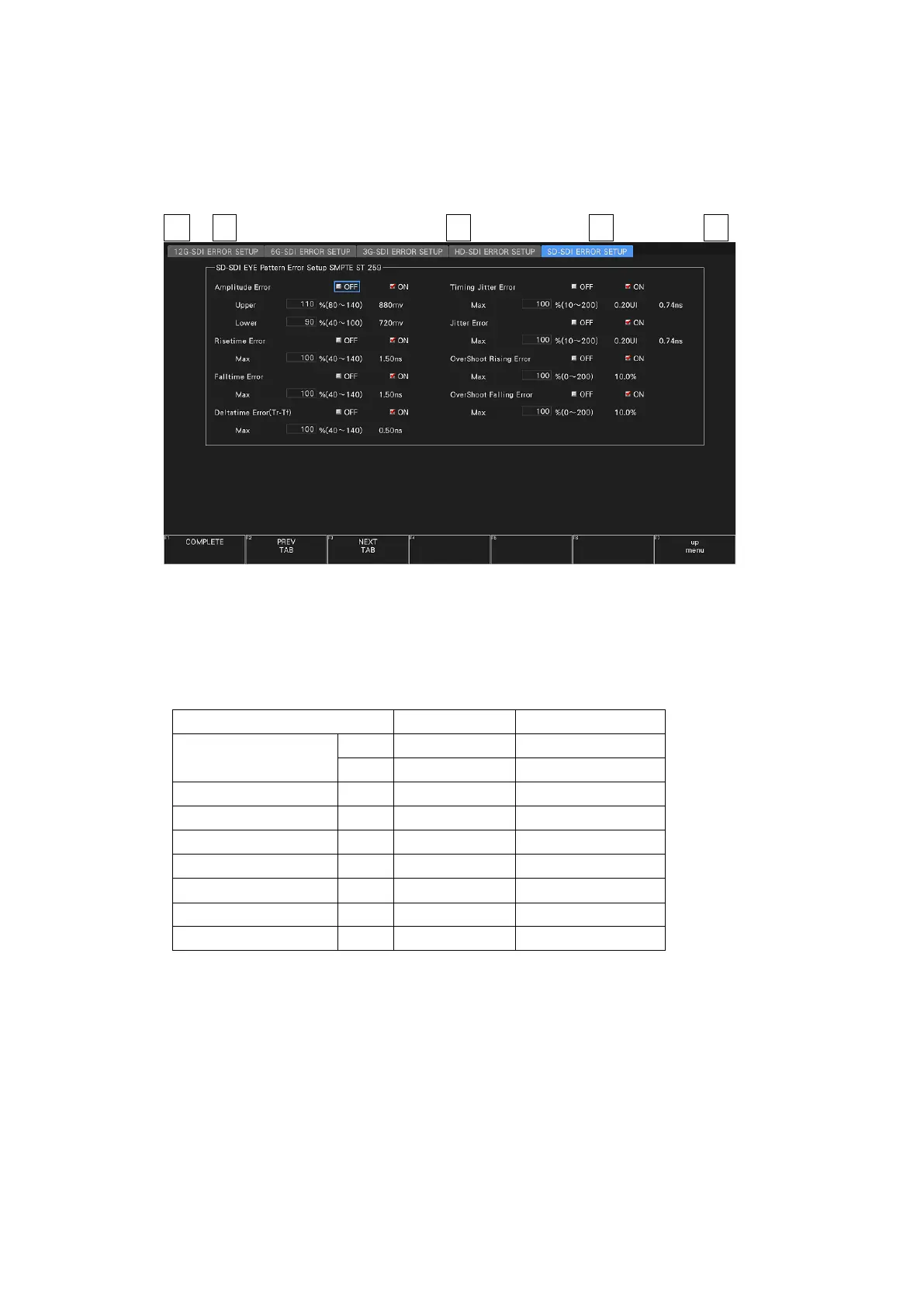
Figure 17-15 SD-SDI ERROR SETUP tab
A configuration example showing threshold values that correspond to SMPTE ST 259 is given
below.
Table 17-7 SD-SDI ERROR SETUP configuration example
Parameter
Setting Example
Corresponding Value
Amplitude Error
Upper
110%
880 mV
Lower
90%
720 mV
Risetime Error
Max
100%
1.50 ns
Falltime Error
Max
100%
1.50 ns
Deltatime Error(Tr-Tf)
Max
100%
0.50 ns
Timing Jitter Error
Max
100%
0.20 UI (0.74 ns)
Jitter Error
Max
100%
0.20 UI (0.74 ns)
Overshoot Rising Error
Max
100%
10.0%
Overshoot Falling Error
Max
100%
10.0%

Table of Contents

Other manuals for Leader LV5300A

Related product manuals