6. BASIC OPERATION
78
6.1.3 Selecting the Displayed Channel
To select the channels to display, follow the procedure below.
Procedure
INPUT
→ F•1 A: ON / OFF
→ F•2 B: ON / OFF
You can also use F•6 INPUT SELECT on each measurement screen to select the display
channels.
F•6 INPUT SELECT works as follows:
• Select the display channel.
• When Through Out(SDI1) on the SDI OUT tab is Selection(1/2), select the signal to output
from SDI OUTPUT 1.
• Selects that channel to be configured when F•6 OPERATE CH MODE of the INPUT menu is
set to INDIVIDUAL.
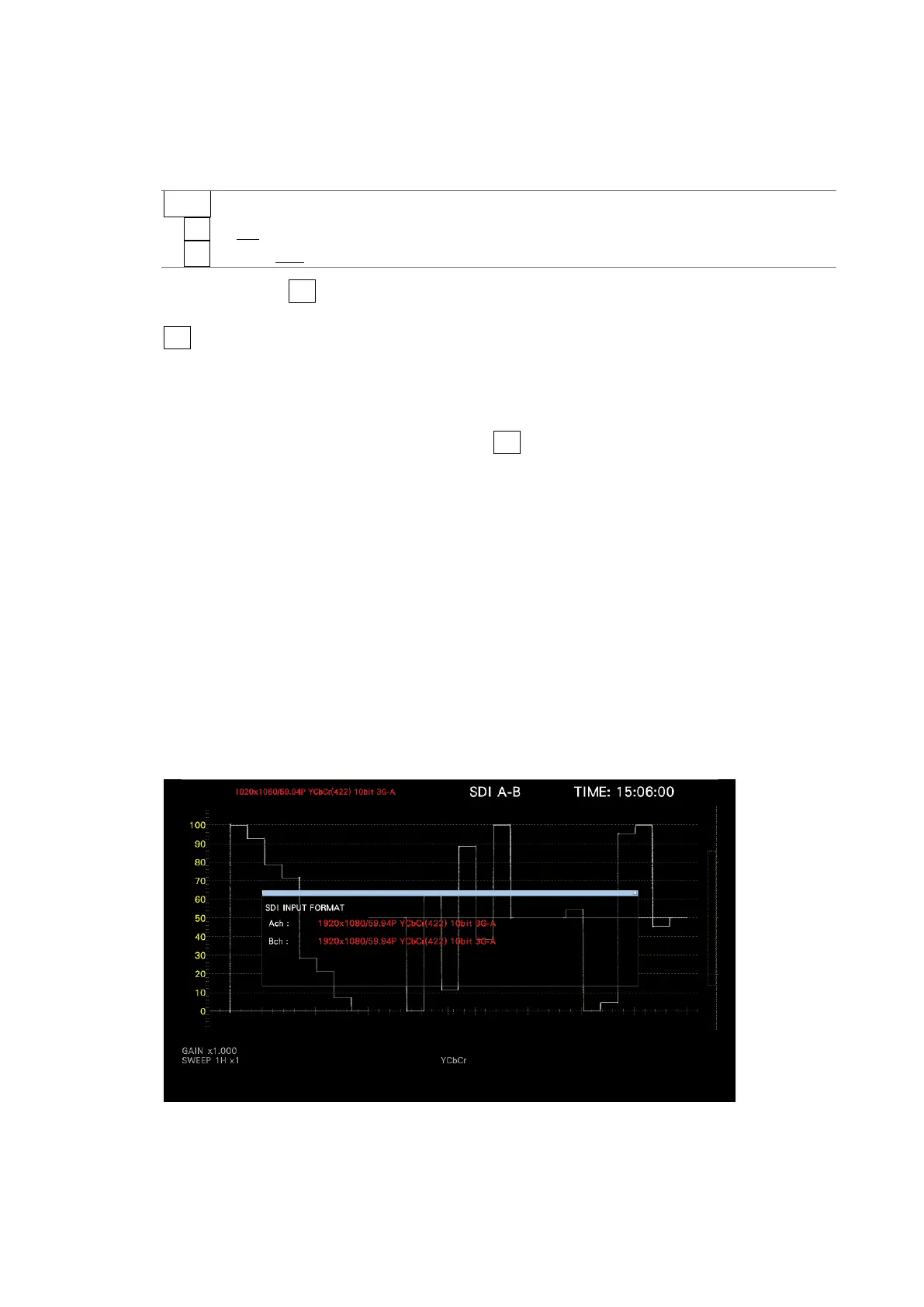
6.1.4 Input Format Error Indication
If the format of the received signal is not appropriate for the setting specified on the SDI IN
SETUP1 tab of the SYS menu, the instrument displays the format in red or an INPUT
FORMAT window in the center of the screen. If this occurs, check the settings on the SDI IN
SETUP1 tab, the input signal, and payload ID.
The format is displayed in red in the following situations.
• If the format is 2 sample interleave of 3G(DL)-4K, and the order of the link is not correct
• When the SDI SYSTEM setting and the payload ID of the input signal are different
• When the payload ID is not appropriate
[See also] SDI IN SETUP1 tab → 7.1.1, “Configuring the SDI Input Connectors.”
Figure 6-2 SDI IN SETUP1 tab