16. Status Display
341
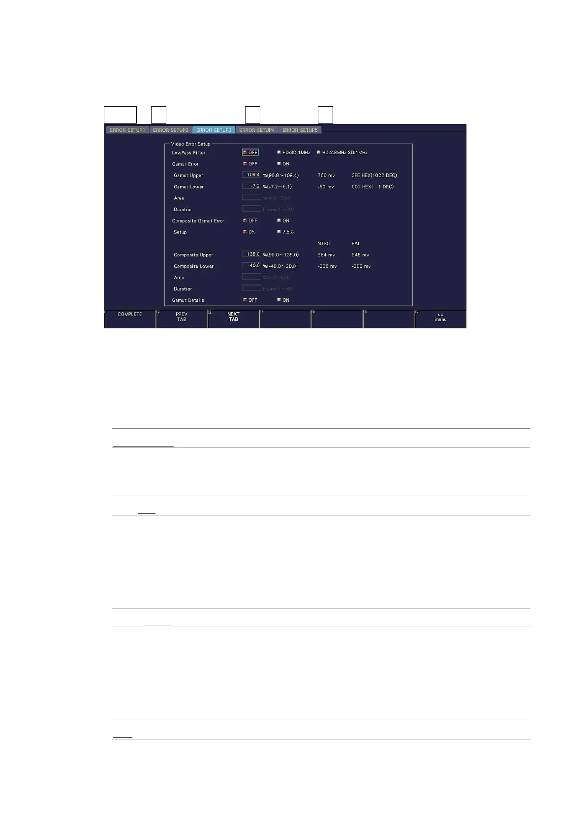
16.2.3 Error Setup 3
In the ERROR SETUP3 tab, configure gamut error settings.
STATUS → F•5 STATUS SETUP → F•2 PREV TAB or F•3 NEXT TAB →
Figure 16-4 ERROR SETUP3 tab
• LowPass Filter
Select the frequency response of the low-pass filter used for gamut error and composite
gamut error detection. Set this to remove transient errors caused by overshoot and other
anomalies.
HD/SD:1MHz / HD:2.8MHz SD:1MHz / OFF
• Gamut Error
Select whether to detect gamut errors.
ON / OFF
• Gamut Upper
Set the gamut error upper limit. An error occurs when the input signal level exceeds the
specified value.
In the 5-bar GBR display, levels that are greater than or equal to the specified value are
displayed in red.
90.8 - 109.4%
• Gamut Lower
Set the gamut error lower limit. An error occurs when the input signal level goes below
the specified value.
In the 5-bar GBR display, levels that are less than or equal to the specified value are
displayed in red.
-7.2 - 6.1%