18. Remote Control
427
18. REMOTE CONTROL
You can use the remote connector on the rear panel to load presets, transmit alarm signals, and
perform other operations. Use your 15-pin D-sub connector to control the instrument.
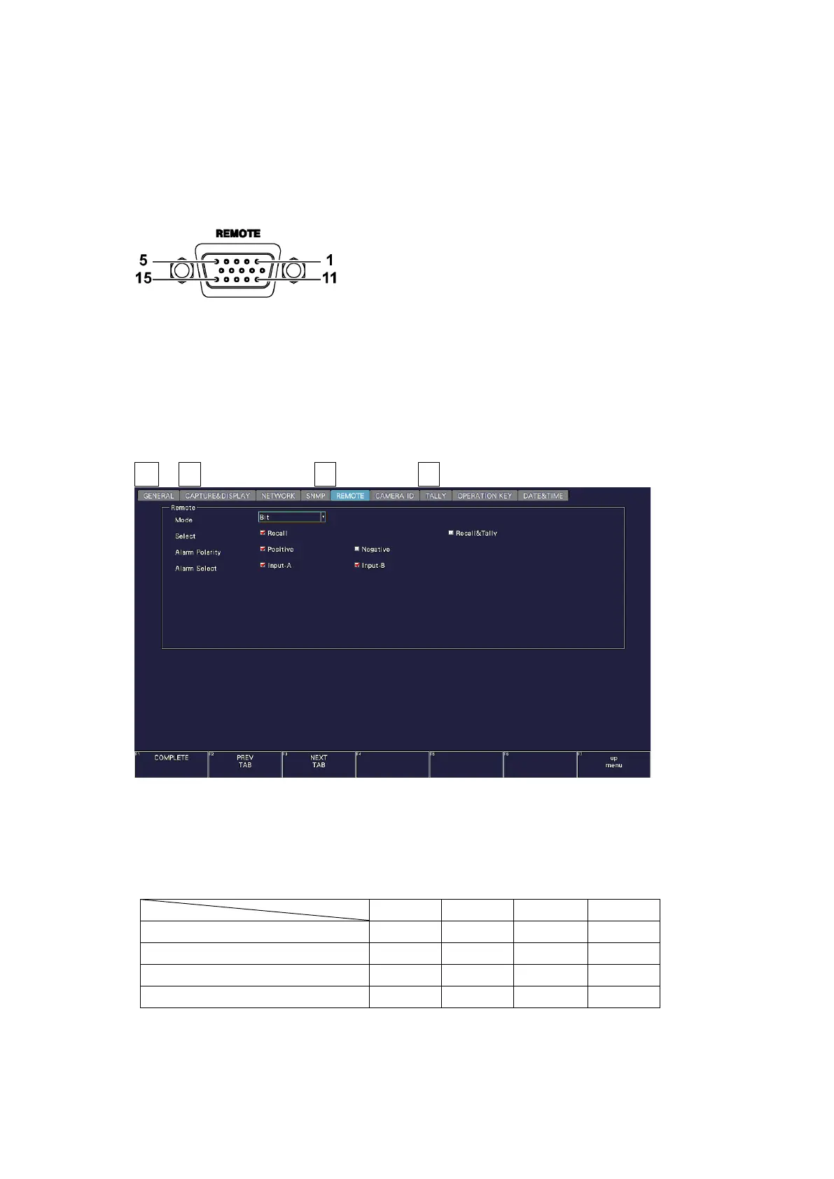
• Remote Connector Diagram
The remote connector diagram as viewed from the rear panel is shown below.
Figure 18-1 Remote connector (female, inch screws)
• Configuring the instrument
To configure the remote control connector, use the SYS menu. See section 7.2.8, “Setting the
Remote Connector.”
To display tallies through the remote connector, an SER27 must be installed and Tally Control
Select must be set to Remote.
SYS → F•2 SYSTEM SETUP → F•2 PREV TAB or F•3 NEXT TAB →
Figure 18-2 REMOTE tab
Each mode on the REMOTE tab is described below. Depending on the selected mode, the
items that can be controlled vary as follows.
Table 18-1 Mode