16. Status Display
367
16.7.3 Setting the Measurement Range
To set the measurement range, follow the procedure below. Use the AV PHASE SETUP tab to
configure these settings.
Procedure
STATUS → F•2 SDI ANALYSIS → F•3 AV PHASE → F•3 AV PHASE SETUP
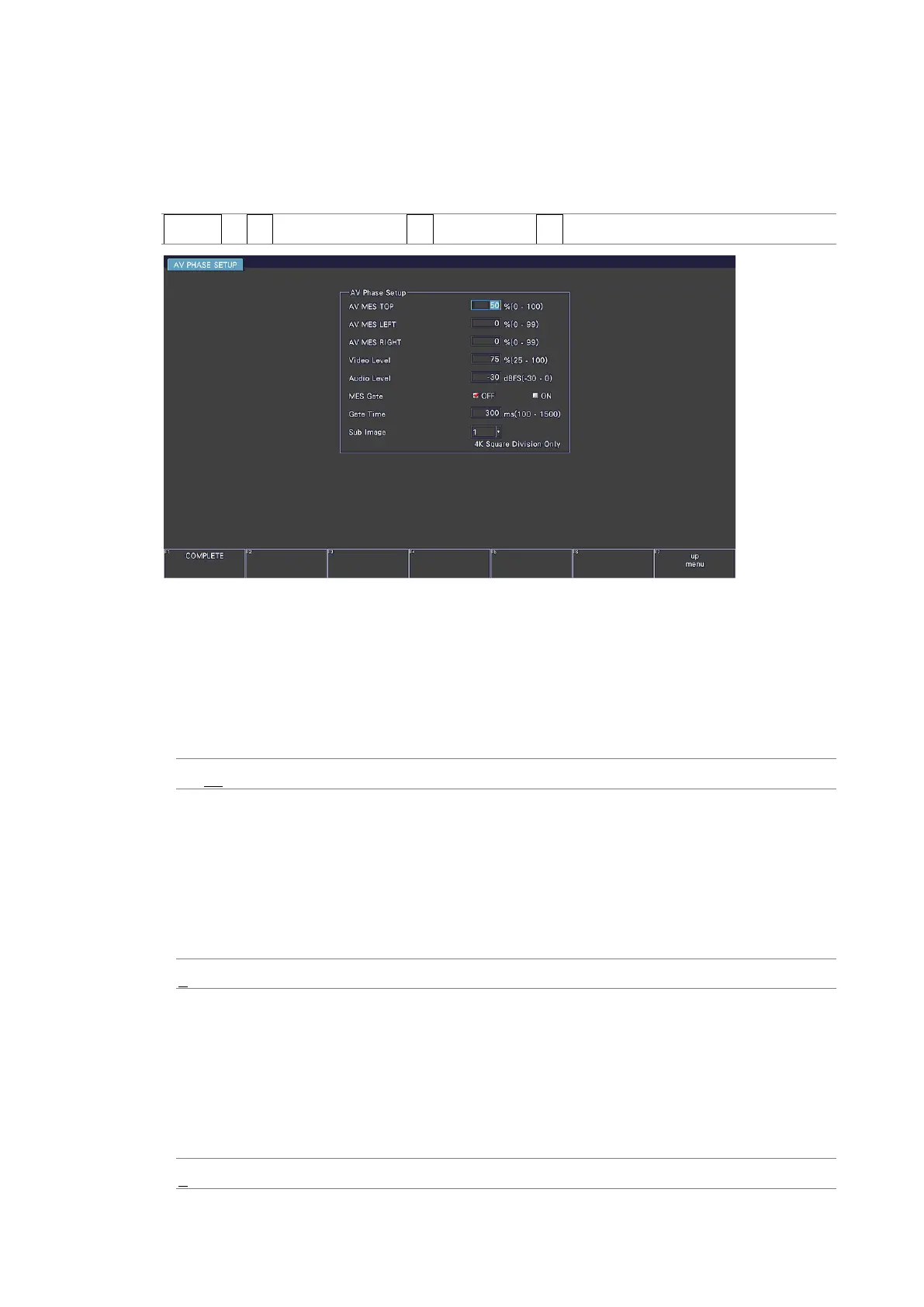
Figure 16-14 AV PHASE SETUP tab
• AV MES TOP
Set the video signal measurement line with the top edge of the picture taken to be 0 %
and the bottom edge to be 100 %.
You can also set this using LINE SELECT on the PIC menu while viewing the picture.
[See also] 13.9.3, “Setting the Lip Sync Measurement Range (SER20)”
0 - 50 - 100%
• AV MES LEFT
Set the video signal measurement range (left side) with the left edge of the picture taken
to be 0 % and the right edge to be 100 %. You cannot set this to the right of the line set
with AV MES RIGHT.
You can also set this using LINE SELECT on the PIC menu while viewing the picture.
[See also] 13.9.3, “Setting the Lip Sync Measurement Range (SER20)”
0 - 99%
• AV MES RIGHT
Set the video signal measurement range (right side) with the right edge of the picture
taken to be 0 % and the left edge to be 100 %. You cannot set this to the left of the line
set with AV MES LEFT.
You can also set this using LINE SELECT on the PIC menu while viewing the picture.
[See also] 13.9.3, “Setting the Lip Sync Measurement Range (SER20)”
0 - 99%