6. BASIC OPERATION
84
6.2.3 Measuring 12G Signals (SER28)
1. On the SDI IN SETUP1 tab of the SYS menu, set SDI System to 4K 12G.
[See also] 7.1.1, “Configuring the SDI Input Connectors”
SYS → F•1 SIGNAL IN OUT → F•2 PREV TAB or F•3 NEXT TAB →
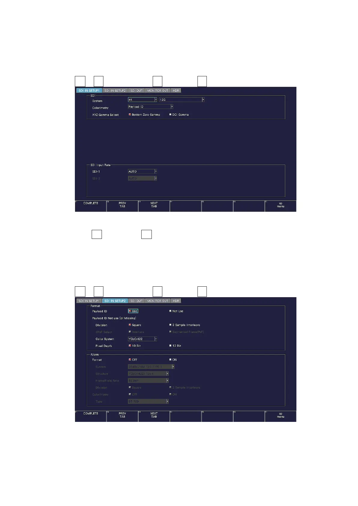
Figure 6-15 SDI IN SETUP1 tab
2. Press F•2 PREV TAB or F•3 NEXT TAB, and under SETTING on the SDI IN SETUP2 tab,
set the payload ID.
Select Use or Not Use. If you select Not Use, set Color System, and Pixel Depth.
[See also] 7.1.3, “Setting the Payload ID”
Only 2 sample interleave is supported for the division transmission system.
SYS → F•1 SIGNAL IN OUT → F•2 PREV TAB or F•3 NEXT TAB →
Figure 6-16 SDI IN SETUP2 tab
3. Press COMPLETE.
4. Apply 12G signals to the SDI INPUT 1 connectors on the rear panel.