12. CIE Chromaticity Diagram Display (SER22)
242
12.1.3 Setting the User-defined Triangle
To set the user-defined triangle, press F•4 USER TRIANGLE on the CIE DIAGRAM SCALE
menu.
Up to two user-defined triangles can be specified. Press F•1 TRIANGLE to select 1 or 2.
VECT → F•2 CIE DIAGRAM SCALE → F•4 USER TRIANGLE →
Figure 12-4 USER TRIANGLE menu
To change the vertex coordinates of the color triangle, follow the procedure below. Press
F•2 PRIMARY COLOR to select the vertex you want to change, and then press F•3 x VALUE
and F•4 y VALUE to set the coordinates. The default setting is equivalent to the BT.2020
coordinates.
Procedure
VECT → F•2 CIE DIAGRAM SCALE → F•5 USER TRIANGLE
→ F•2 PRIMARY COLOR: G / B / R
→ F•3 x VALUE: 0.000 - 0.170 - 1.000
→ F•4 y VALUE: 0.000 – 0.797 - 1.000
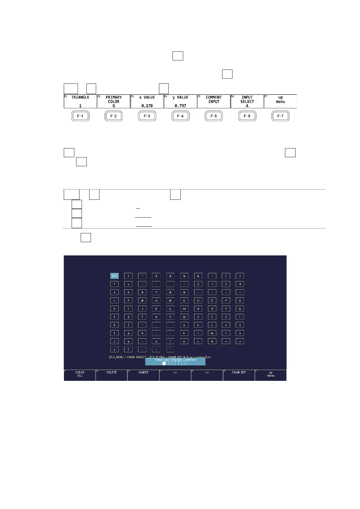
Press F•5 COMMENT INPUT to assign names of your choice to user-defined triangles.
Enter up to 8 characters.
Figure 12-5 Triangle name input screen