7. SYSTEM SETTINGS
153
• Select (SER27)
When Mode is Bit or Binary, select the function to assign to pin 10 (/ACH), pin 11 (/BCH),
pin 12 (/CCH), and pin 13 (/DCH) of the remote connector. When Mode is Command or
Tally, select Recall.
This does not appear when SER27 is not installed.
Recall: Assign preset recalling.
Recall&Tally: Assigned tally control.
• Alarm Polarity
Select the alarm output polarity.
Positive: A high signal is transmitted when an error is detected.
Negative: A low signal is transmitted when an error is detected.
• Alarm Select
Select the display channel that errors are detected on for transmitting alarms.
By default, all the check boxes are selected.
Input-A / Input-B
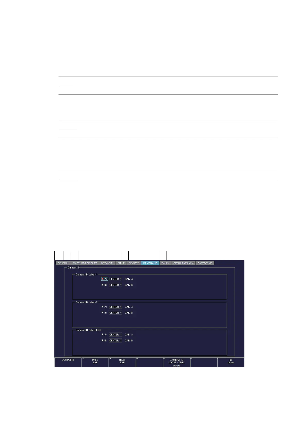
7.2.11 Setting the Camera ID (SER27)
Use the CAMERA ID tab to select the placement of the camera ID and set the label.
The procedures for Camera ID Label-1, Camera ID Label-2, and Camera ID Label-IRIS are
the same.
The settings that you specify here (except the placement selection and label setting) will not
be initialized even if you initialize the instrument. In addition, they are not recorded to
presets.
SYS → F•2 SYSTEM SETUP → F•2 PREV TAB or F•3 NEXT TAB →
Figure 7-21 CAMERA ID tab