13. Picture Screen
283
10. Turn the function dial (F•D) to select the copy source file from the USB memory device.
11. Press F•3 FILE LOAD.
The user-defined correction table that you selected is copied from the USB memory to
USER_A. The copy operation is complete when the file list screen disappears and the
display returns to the measurement screen.
If a file has already been stored to USER_A, an overwrite confirmation prompt appears.
If you want to overwrite the current file, press F•1 OVER WRITE YES. Otherwise, press
F•3 OVER WRITE NO.
After you have copied a user-defined correction table, you can select it by pressing F•1
GAMMA SELECT in the CINELITE menu. A loaded correction table is displayed using the
name determined by its NAME keyword.
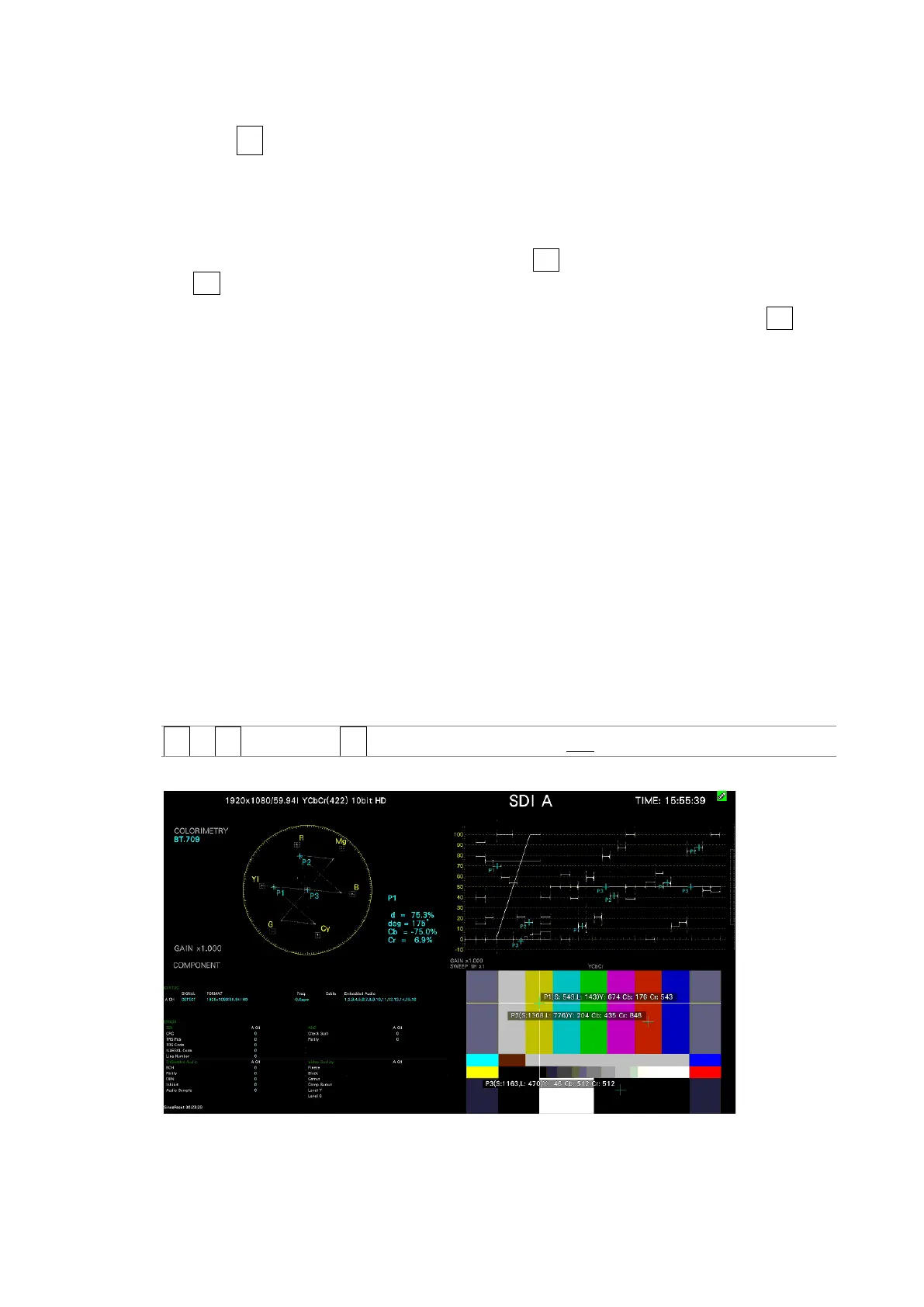
13.6.8 Displaying Link Markers
To synchronize the markers on the vector screen and video signal waveform screen to
measurement points P1 to P3 and REF that you specify on the CINELITE screen, follow the
procedure below.
Synchronized markers can be displayed only when an f Stop screen or % DISPLAY screen is
shown in the same multi-screen display.
Markers cannot be displayed on the video signal waveform in the following situations.
• When SWEEP is set to V or H SWEEP is set to 2H in the video signal waveform menu
• When COLOR MATRIX in the video signal waveform menu is COMPOSIT
Marker display will not work properly when waveforms are being displayed using an external
sync signal.
Procedure
PIC → F•2 CINELITE → F•4 CINELITE ADVANCE: ON / OFF
CINELITE ADVANCE = ON
Figure 13-27 Displaying link markers