11. VECTOR DISPLAY
225
11.9.2 Configuring the Variable Marker
When the VARIABLE SCALE is set to on, you can use F•4 VARIABLE MARKER to configure
the variable marker.
[See also] VARIABLE SCALE → Section 11.3.7, “Turning the Variable Scale On and Off”
VECT → F•4 VARIABLE MARKER →
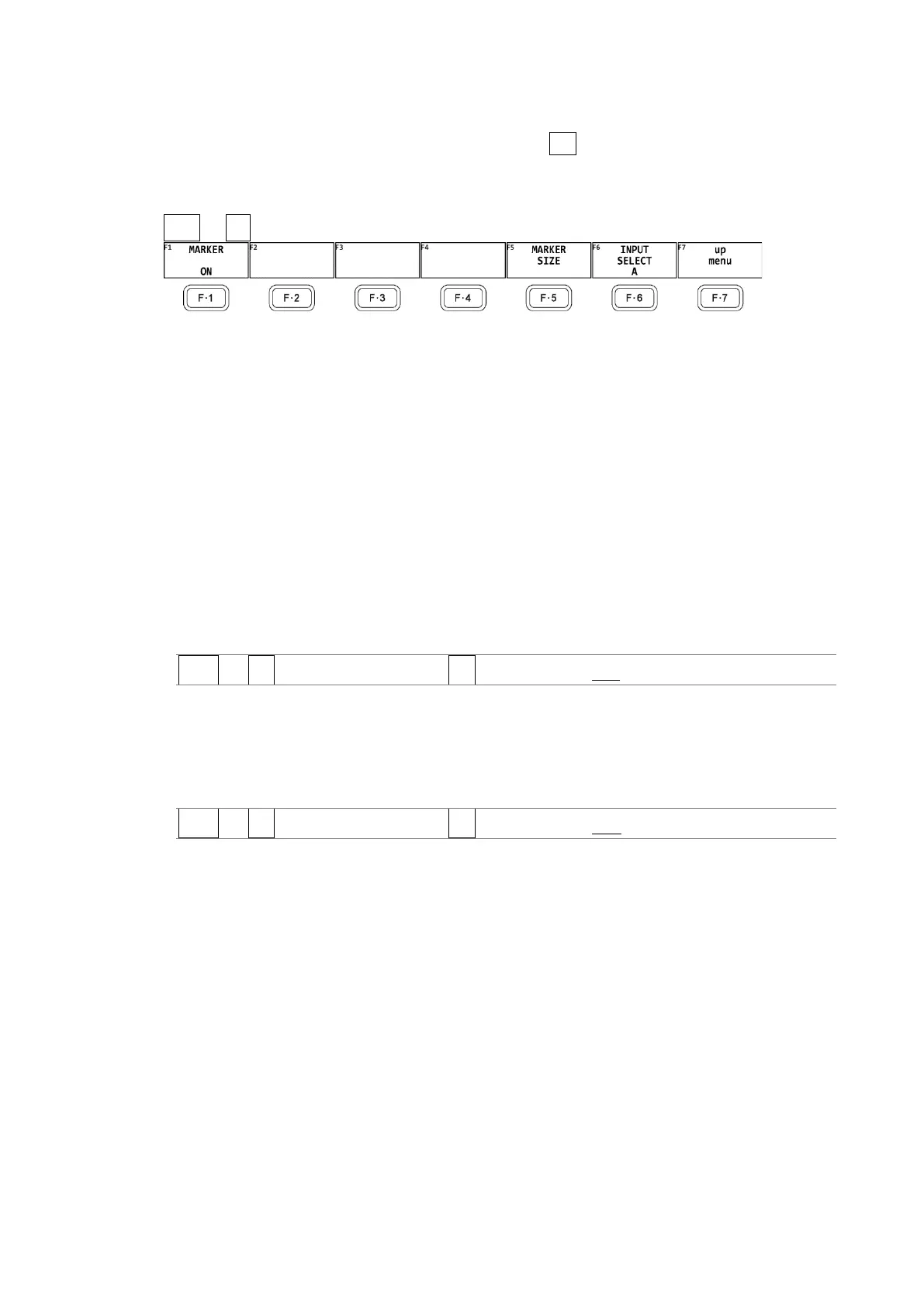
Figure 11-15 VARIABLE MARKER menu
• Turning the Display On and Off
To display the variable marker on the vector display, follow the procedure below.
[See also] VARIABLE SCALE → Section 11.3.7, “Turning the Variable Scale On and Off”
You can move the marker horizontally using the H POS knob and vertically using the V
POS knob. The measured values are displayed in the lower right of the display. Press the H
POS knob to move the marker to the Cb = 0.0% position. Press the V POS knob to move
the marker to the Cr = 0.0% position.
Measured values are displayed using the following references: Cb at position B = 100.0%
and Cr at position R = 100.0%. The distance from the center is expressed as “d,” and hue
is expressed as “deg.”
Procedure
VECT → F•4 VARIABLE MARKER → F•1 MARKER: ON / OFF
• Configuring the Marker Size
To configure the size of the marker and frame, follow the procedure below. It can be
configured even if the variable marker is set to off.
Procedure
VECT → F•4 VARIABLE MARKER → F•5 MARKER SIZE: 5 % - 10 %