17. Eye Pattern Display (LV5300/LV5300A/LV7300-SER02)
404
17.8 Configuring Error Detection Settings
Use F•1 EYE/JITTER INTEN/CONFIG → F•5 ERROR SETUP on the EYE menu to set error
detection.
When error detection is set to ON, the following actions are performed when an error occurs.
• Displays measured values on the eye pattern display and jitter display in red
• Displays errors in the event log of the status display
• Displays “ERROR” in the upper right of the display.
• Transmits a signal from the alarm output remote terminal
[See also] Section 16.4.1, “Event Log Screen Description”
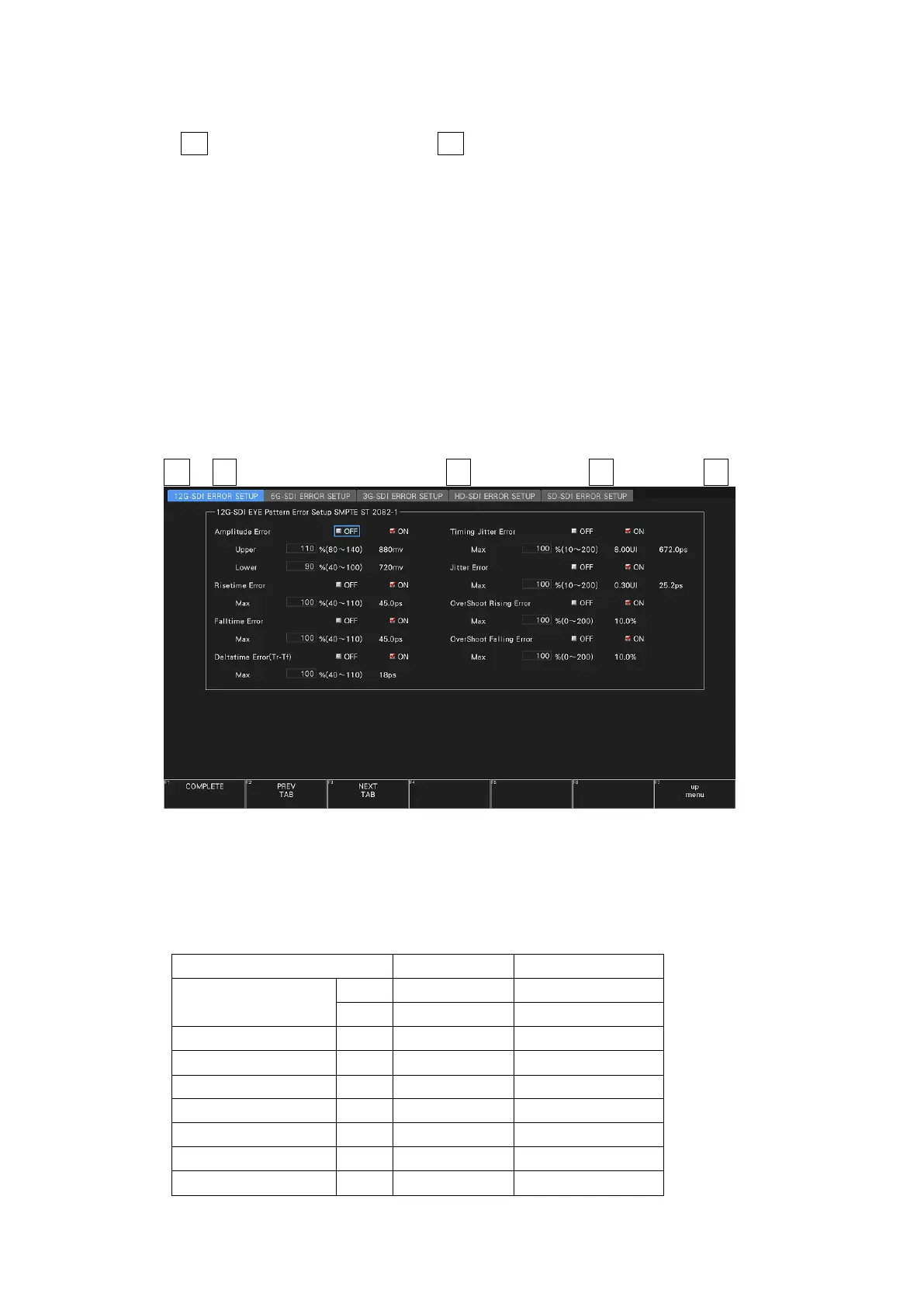
17.8.1 Configuring 12G Error Settings
Use the 12G-SDI ERROR SETUP tab to configure error detection settings for 12G signals.
You can set the threshold values when you set the error detection to ON. Measured values
given in SMPTE ST 2082-1 are used as 100 %.
EYE → F•1 EYE/JITTER INTEN/CONFIG → F•5 ERROR SETUP → F•2 PREV TAB or F•3 NEXT TAB →
Figure 17-11 12G-SDI ERROR SETUP tab
A configuration example showing threshold values that correspond to SMPTE ST 2082-1 is
given below.
Table 17-3 12G-SDI ERROR SETUP configuration example