10. Video Signal Waveform Display
199
10.5.5 Displaying the Blanking Interval
To set how the waveforms in the blanking interval are displayed, follow the procedure
below.
If a setting other than REMOVE is selected, the vertical blanking interval is also displayed on
the vector display.
[See also] COLOR MATRIX → section 10.8.1, “Selecting the Color Matrix.”
Procedure
WFM → F•3 SWEEP → F•5 BLANKING: REMOVE / V VIEW / H VIEW / ALL VIEW
Settings
REMOVE: Only the active interval is displayed.
V VIEW: The active interval and the vertical blanking interval are displayed.
H VIEW: The active interval and the horizontal blanking interval are displayed.
This option cannot be selected when COLOR MATRIX is set to
COMPOSITE.
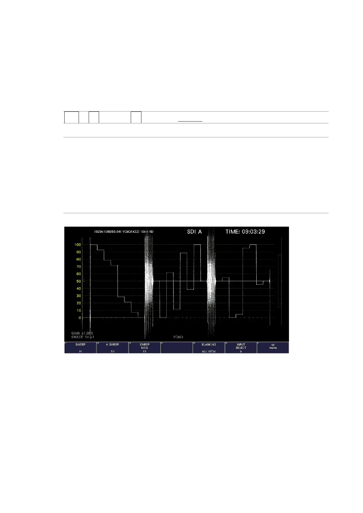
ALL VIEW: The entire input signal is displayed.
This option cannot be selected when COLOR MATRIX is set to
COMPOSITE.
BLANKING = ALL VIEW
Figure 10-20 Displaying blanking intervals