18. Remote Control
429
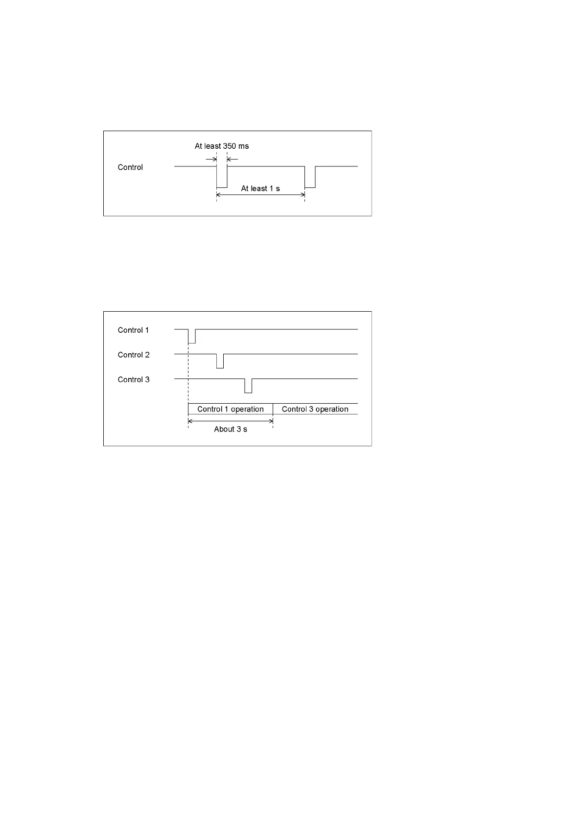
• Control
The input connectors respond to active-low signals. Do not apply negative voltages or
voltages that exceed +5 V. The active-low signal must be stable for at least 350 ms. After
that, wait at least 1 second before applying the next signal.
Figure 18-3 Control timing 1
After a setting is made, it may take about 3 seconds for the operation to finish. If you
configure subsequent settings before the initial operation finishes, only the last setting will
take effect. All settings in between will be discarded. (In the following example, control 2
will be discarded.)
Figure 18-4 Control timing 2
• Recalling a Preset
You can use pins 2 to 9 of the remote connector to load presets.
In Bit mode, presets 1 to 8 can be recalled out of presets 1 to 60. Set the number to recall
to low level.
• Switching Display Channels
You can use pins 10 to 13 of the remote connector to switch the display channel.
Channels that you set to low will be turned on, and channels that you set to high will be
turned off. However, in single input mode, you cannot turn multiple channels on.
• Alarm output
An alarm is transmitted from pin 14 of the remote connector in the following situations.
The alarm output applies to A/B channels. However, when measuring 3G(DL)-4K, alarms are
output only for the currently displayed channels.