4. PANEL DESCRIPTION
57
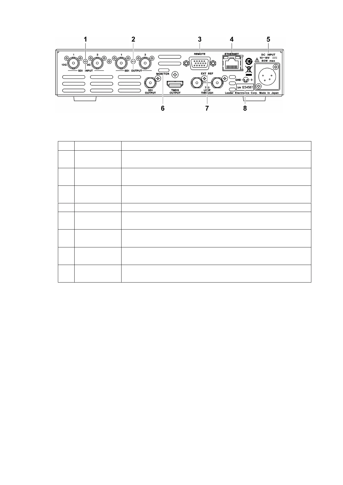
Figure 4-6 LV7300 rear panel (SER01/SER02)
Table 4-4 LV7300 rear panel description
SDI signal input connectors.
[See also] 5.4.1, “SDI Signal I/O.”
SDI signal output connectors
[See also] 5.4.1, “SDI Signal I/O.”
15-pin D-sub remote connector. This can be used to execute actions such as
recalling preset settings.
Ethernet port. Supports TELNET, FTP, SNMP, HTTP, and SNTP.
DC inlet.
[See also] 5.1, “Turning the Instrument On and Off”
Transmits the screen image.
[See also] 5.4.3, “Transmitting Monitor Signals”
External reference input connector. This is a loop-through connector.
[See also] 5.4.2, “External Sync Signal Input”
The serial number is printed on this label.