d-Color MF4003/MF3303
F DISASSEMBLY/REASSEMBLY > 4. d-Color MF4003/MF3303
F-31
6. To reinstall, reverse the order of removal.
7. NOTE
▪ Since the counter will be cleared when the backup board is replaced with a new one, replace the following parts with new
ones.
▪ When the transfer belt unit, transfer roller and the fusing unit have been replaced with new ones, perform [New Release] in
the service mode.
▪ Imaging unit/Y,M,C,K
▪ Transfer belt unit
▪ Fusing unit
▪ Transfer roller
▪ Feed roller, pick-up roller, separation roller (including options)
▪ Separation pad
▪ Toner filter
NOTE
▪ When the new backup board is installed, the error message: "License management error occurred." is displayed. Conduct
the i-Option recovery operation.
8. Open the front door and turn on the main power switch.
9. Enter the Service Mode. Make individual adjustments shown in Table 1: Readjustment items in the order listed, using the machine
management list and the adjustment lists that were output at the time of main body installation and maintenance.
NOTE
▪ Ensure the front door is opened.
NOTE
▪ Conduct the readjustment of the above adjustment items before the starting the initial warm-up operation after replacing the
backup board.
10. Turn OFF the main power switch.
11. Turn ON the main power switch and close the front door. Check to see that warm-up and image stabilization operations are completed
normally.
12. Enter the Service Mode again. Make individual adjustments shown in Table 2: Readjustment items in the order listed, using the machine
management list and the adjustment lists that were output at the time of main body installation and maintenance.
13. Select [Service Mode] -> [EnhancedSecurity] -> [Engine FW DipSW] and set the keys of Table 3: Valid switch No. to ON (highlight).
Table 1: Readjustment items
Adjustment
items
Service mode readjustment items Ref. Page
1 Machine Printer Area I.5.3.1 Leading Edge
Adjustment
2 I.5.3.2 Printer Image Centering
Side 1
3 I.5.3.3 Leading Edge Adj. Side
2 (Duplex)
4 I.5.3.4 Prt. Image Center. Side
2 (Dup)
5 System 2 Unit Change Near Empty Display Timing I.10.4.2 Warning display
Table 2: Readjustment items
Adjustment
items
Service mode readjustment items Ref. Page
1 Machine Main Scanning Direction Zoom I.5.6 Main Scanning Direction
Zoom
Table 3: Valid switch No.
Region Valid switch No.
Japan [14], [48], [50]
North America [14], [25], [48], [50]
Europe [14], [46], [48], [50]
Other than the above [14], [48], [50]
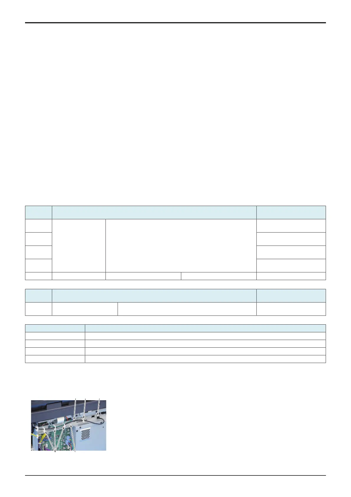
4.3.6TPM board (TPMB)
1. Remove the rear cover.
F.4.1.3 Rear cover
2. Remove the cable and ground wire from four wire saddles [1], and disconnect
the connector [2].
3. Remove the screw [3], and remove the plate [4].

 Loading...


