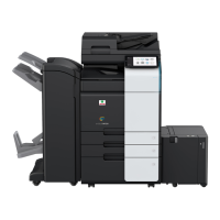
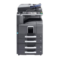
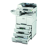
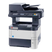
d-Color MF4003/MF3303
L TROUBLESHOOTING > 1. JAM CODE
L-7
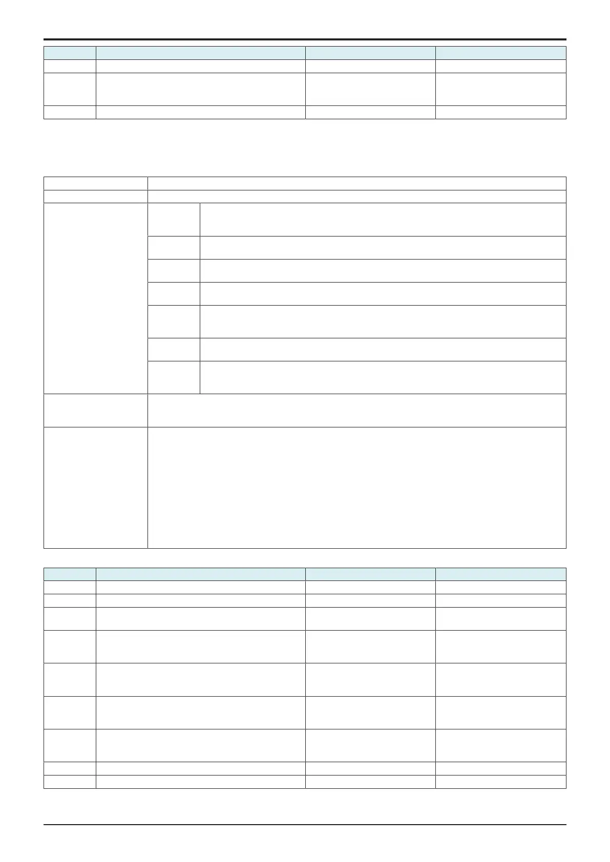
Step Action Control signal Location of electrical component
• Multi code: 2
5 M1/3 load check
• Check code: 28
• Multi code: 3, 4
PCCB/3 CN4-1 to 7 18-P
6 Replace PCCB/3. - -
1.62#-##
1.6.120-02, 20-10, 20-11, 20-12, 20-21, 20-26
Contents
JAM type Misfeed at vertical transport section (When PF-P20 or PF-P21 is installed)
JAM code 20-02, 20-10, 20-11, 20-12, 20-21, 20-26
JAM detection timing 20-02 For paper fed from the tray 2/3, loop forming has not been complete before a sheet enters the
registration roller because the rise timing of load to perform registration is earlier than the rise timing
of load to form a loop.
20-10 The leading edge of the paper is not turned OFF (blocked) the tray 2 transport sensor (PS6/2) even
after the lapse of a given period of time after the tray 2 starts to feed paper.
20-11
The leading edge of the paper is not turned OFF (blocked) the tray 3 transport sensor (PS6/3) even
after the lapse of a given period of time after the tray 3 starts to feed paper. (d-Color MF4003 only)
20-12
The leading edge of the paper is not turned OFF (blocked) the tray 2 transport sensor (PS6/2) even
after the lapse of a given period of time after the tray 3 starts to feed paper. (d-Color MF4003 only)
20-21
The leading edge of the paper is not turned ON (unblocked) the tray 2 transport sensor (PS6/2)
even after the lapse of a given period of time after the tray 3 starts to feed paper. (d-Color
MF4003 only)
20-26 The leading edge of the paper is not turned ON (blocked) the registration sensor (PS9) even after
the lapse of a given period of time after the tray 2/3 starts to feed paper.
- Paper jam of a sheet of paper left at the vertical transport section results, if a sheet of paper is
determined to exist at a position detected when the main power switch is turned ON, a door is
opened and closed, or a misfeed or malfunction is reset.
Misfeed processing
location
• Right door
• Tray 2 right door
• Tray 3 right door
Relevant parts • Main motor (M1)
• Tray 2 drive motor (M1/2)
• Tray 3 drive motor (M1/3)
• Registration clutch (CL4)
• Tray 2 transport clutch (CL2/2)
• Tray 3 transport clutch (CL2/3)
• Registration sensor (PS9)
• Tray 2 transport sensor (PS6/2)
• Tray 3 transport sensor (PS6/3)
• Base board (BASEB)
• Tray 2 PC control board (PCCB/2)
• Tray 3 PC control board (PCCB/3)
Procedure
Step Action Control signal Location of electrical component
1 Initial check items - -
2 PS9 I/O check, sensor check BASEB CN22EA-13 (ON) 13-C
3 PS6/2, PS6/3 I/O check, sensor check PCCB/2 CN3-3 (ON)
PCCB/3 CN3-3 (ON)
17-X
4 CL4 load check
• Check code: 21
• Multi code: 3
BASEB CN22EA-3 (ON) 12-C
5 CL2/2, CL2/3 load check
• Check code: 21
• Multi code: 1, 2
PCCB/2 CN5-1 (ON)
PCCB/3 CN5-1 (ON)
15-P
6 M1 load check (Main body)
• Check code: 40
• Multi code: 1, 2
BASEB CN17E-1 to 5 1-C
7 M1/2, M1/3 load check
• Check code: 28
• Multi code: 1, 2, 3, 4
PCCB/2 CN4-1 to 7
PCCB/3 CN4-1 to 7
18-P
8 Replace PCCB/2 or PCCB/3. - -
9 Replace BASEB. - -

 Loading...
