d-Color MF4003/MF3303
I SERVICE MODE > 13. State Confirmation
I-65
• If the value is Low: In IDC detection, the image density is judged as high, thus the Vg/Vdc value is to be adjust lower.
Display item Reference value
Vdc Around -0 V to -800 V.
Vg Around 0 V to -1600 V.
LD Light Value
• Shows the LD light value of toner during print image formation.
Charging DC Output Value
• Shows the DC current value applied to the charging roller of toner during print image formation.
Charging AC Output Value 1
• Shows the AC voltage value applied to the charging roller of toner during print image formation.
Charging AC Output Value 2
• Shows the current value applied to the charging roller of toner during print image formation.
13.3Level History 1
• To display TCR (T/C ratio), IDC/registration sensor output values, and fusing temperature.
• Used for troubleshooting of image problems.
Display item Contents
TCR-C/-M/-Y/-K Shows the T/C output reading taken last. (*)
IDC Shows the latest IDC data.
Middle heat temperature Displays the latest detected temperature of the heating temperature
sensor.
Medium Heating Temperature Displays the latest detected temperature of the heating roller
thermistor/Ctr.
Heat edge temperature Displays the latest detected temperature of the heating roller
thermistor/Edg.
• *: “Reading taken last” means
• Density of toner of the latest image.
• When a test pattern is produced by pressing the Start key while level history 1 is being displayed.
13.4Level History 2
• IDC Sensor (Transfer belt bare surface level) as adjusted through the image stabilization sequence and ATVC value.
• Used for troubleshooting of image problems.
Display item Contents
IDC Sensor Adjust 1 Shows the intensity adjustment value of the IDC sensor. (0 to 1023)
1st Transfer Output Value Shows the first image transfer nearest output value. (0 to 2700)
2nd Transfer Output Value Shows the second image transfer nearest output value. (-500 to 4500 V)
13.5Temp. & Humidity
• Displays the temperature, humidity and PH temperature in the machine.
• Used as reference information when a malfunction occurs.
Display item Contents
Temp-Inside 0 to 80 °C in 1 °C increments
Humidity 10 to 90 % in 1 % increments
PH temperature 0 to 100 °C in 1 °C increments
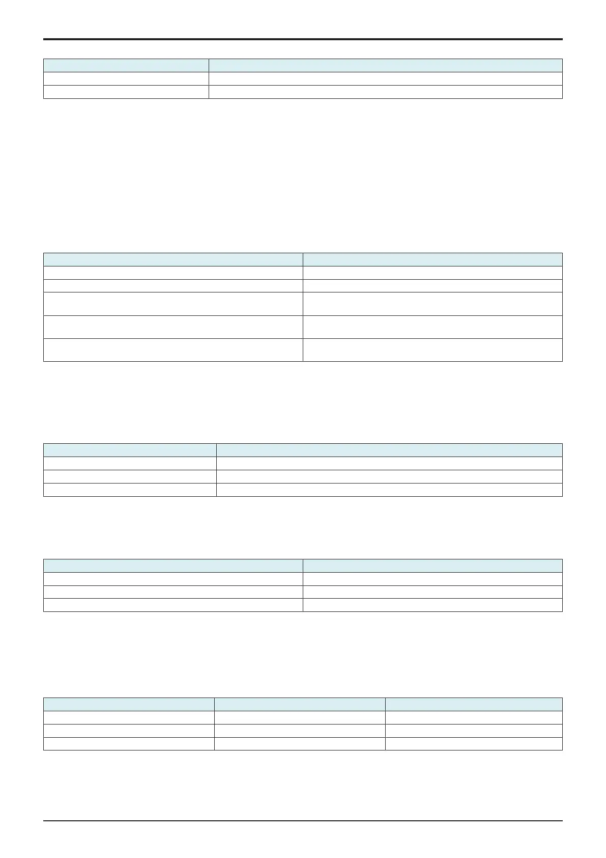
13.6CCD Check
• To display the D/A value of CCD clamp/gain for R, G, and B.
• Used for troubleshooting for the CCD sensor/CIS.
CCD Check
• CLAMP: 0 (remain static)
• GAIN: The maximum value and the minimum value of the output value should be within the range shown below.
Acceptable gain range Minimum value Maximum value
R 20 238
G 10 222
B 70 247

 Loading...


