d-Color MF4003/MF3303
P THEORY OF OPERATION > 2. PF-P20/PF-P21
P-68
2. PF-P20/PF-P21
2.1Configuration
[4]
[15]
[14]
[16]
[3]
[2]
[1]
[13]
[5]
[6]
[7]
[8]
[12]
[10]
[9]
[11]
[1] Tray 2 paper feed clutch (CL1/2) [2] Tray 2 transport clutch (CL2/2)
[3] Tray 2 upper limit sensor(PS2/2) [4] Feed roller
[5] Tray 2 transport sensor (PS6/2) [6] Separation roller
[7] Tray 2 paper feed sensor (PS3/2) [8] Tray 2 door sensor (PS4/2)
[9] Tray 2 paper empty sensor(PS1/2) [10] Edge guide plate
[11] Trailing edge guide plate [12] Paper lift-up plate
[13] Tray 2 lift-up motor (M2/2) [14] Tray 2 PC control board (PCCB/2)
[15] Tray 2 drive motor (M1/2) [16] Pick-up roller
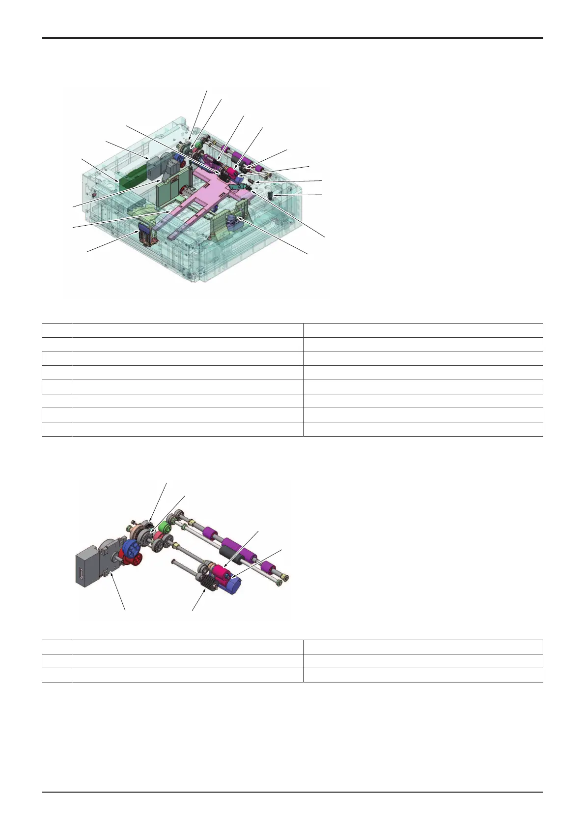
2.2Drive
[1] Tray 2 paper feed clutch (CL1/2) [2] Tray 2 transport clutch (CL2/2)
[3] Feed roller [4] Separation roller
[5] Pick-up roller [6] Tray 2 drive motor (M1/2)
2.3Operation
2.3.1Up/down control
• Tray 2 and tray 3 are controlled in the same control procedure.
(1)Up operation
• The paper lift-up lever is located under the paper lift-up plate.
• The drive shaft of the tray 2 lift-up motor is connected to the paper lift-up lever.
• When the drive shaft of the tray 2 lift-up motor rotates, the paper lift-up lever rotates to raise the paper lift-up plate.

 Loading...


