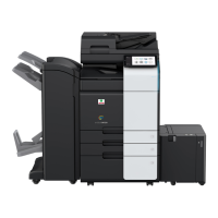
d-Color MF4003/MF3303
L TROUBLESHOOTING > 3. TROUBLE CODE
L-51
• Multi code: 1, 2
• Control signal: BASEB CN17E-11 to 15
• Location of electrical component: 1-C
4. Replace M2.
5. Replace BASEB.
3.13.17C7604
Contents
Trouble type C7604: Power line A4 error
Rank C
Trouble detection condition The fuse detection unit detected an error for a predetermined time.
Trouble isolation -
Relevant electrical parts • Fusing motor (M3)
• Base board (BASEB)
Procedure
1. BASEB F19E conduction check
2. Check the connector between M3-BASEB CN17E for proper connection and correct as necessary.
3. M3 load check
• Check code: 45
• Multi code: 1, 2, 3
• Control signal: BASEB CN17E-6 to 10
• Location of electrical component: 1-C
4. Replace M3.
5. Replace BASEB.
3.13.18C7605
Contents
Trouble type C7605: Power line A5 error
Rank C
Trouble detection condition The fuse detection unit detected an error for a predetermined time.
Trouble isolation -
Relevant electrical parts • High voltage unit (HVPS)
• Base board (BASEB)
Procedure
1. BASEB F6E conduction check
2. Check the connector between HVPS-BASEB CN4E for proper connection and correct as necessary.
3. Replace HVPS.
4. Replace BASEB.
3.13.19C7607
Contents
Trouble type C7607: Power line A7 error
Rank C
Trouble detection condition The fuse detection unit detected an error for a predetermined time.
Trouble isolation -
Relevant electrical parts • 1st transfer pressure clutch (CL1)
• Bypass tray paper feed clutch (CL2)
• Tray 1 paper feed clutch (CL3)
• Registration clutch (CL4)
• ADU transport clutch (CL5)
• ADU forward rotation clutch (CL6)
• ADU reverse rotation clutch (CL7)
• Exit path switch solenoid (SD1)
• Base board (BASEB)
Procedure
1. BASEB F4E conduction check
2. Check the connector between CL1-relay CN13-BASEB CN18E for proper connection and correct as necessary.
3. Check the connector between CL2-relay CN46-BASEB CN23E for proper connection and correct as necessary.
4. Check the connector between CL3-relay CN44-BASEB CN22E for proper connection and correct as necessary.
5. Check the connector between CL4-relay CN45-BASEB CN22E for proper connection and correct as necessary.
6. Check the connector between CL5-relay CN47-BASEB CN23E for proper connection and correct as necessary.
7. Check the connector between CL6-relay CN11-BASEB CN18E for proper connection and correct as necessary.
8. Check the connector between CL7-relay CN39-BASEB CN18E for proper connection and correct as necessary.
9. Check the connector between SD1-relay CN12-BASEB CN18E for proper connection and correct as necessary.
10. CL1 conduction check
• Control signal: BASEB CN18E-4 (ON)
• Location of electrical component: 2-C

 Loading...
