d-Color MF4003/MF3303
P THEORY OF OPERATION > 9. CU-202
P-110
9. CU-202
9.1CONFIGURATION
9.1.1Configuration
• The exhaust port is mounted to cover each suction duct. Thus, the clean unit can maximally collect UFP that is exhausted from the main
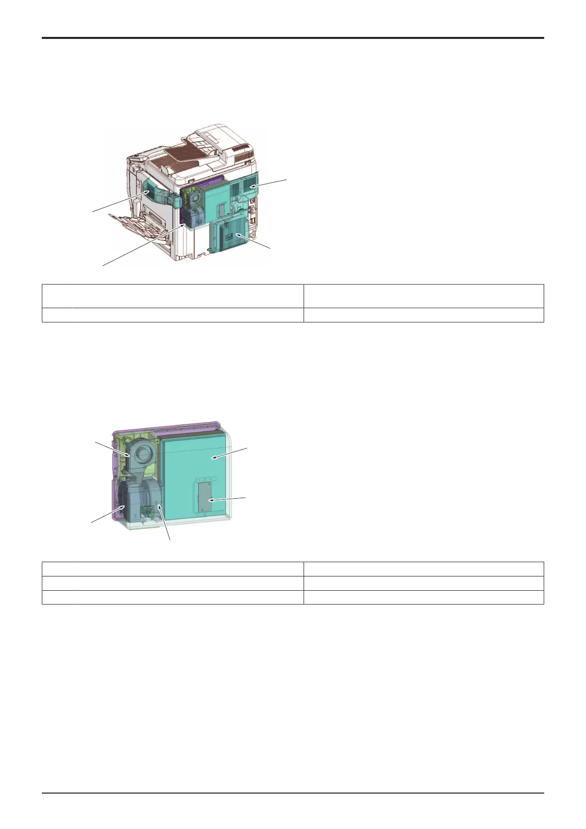
body.
[1] Suction port (paper exit / developing / power supply
section)
[2] Suction port (cooling section)
[3] Clean unit [4] Suction port (fusing section)
NOTE
▪ When the clean unit has been mounted, be sure to configure related settings in service mode. [Service Mode] -> [System 2] ->
[Cleaning Unit Setting]
9.1.2Unit internal configuration
• The clean unit consists of three exhaust fans, a UFP filter, and a drive board.
[1] UFP filter [2] Clean unit drive board (CUDB)
[3] Exhaust fan/2 (FM2) [4] Exhaust fan/3 (FM3)
[5] Exhaust fan/1 (FM1) - -
9.2OPERATION
9.2.1Airflow
• Air is exhausted from the fusing section, paper exit section, and power supply section of the main body, and inside of the machine. The
clean unit takes the exhausted air into the clean unit via each duct.
• The UFP filter collects the air UFP (Ultrafine Particle) that is exhausted from the main body.
• Air passing through the UFP filter is exhausted out of the machine through the exhaust fans 1/2/3 in the clean unit.
NOTE
▪ The UFP filter does not require a periodic replacement.

 Loading...


